What’s new in Simcenter Flotherm 2410?
I introduce new enhancements in Simcenter Flotherm 2410 software release, including easier PCB thermal analysis results visualization, reduced order modeling improvements, and viewing of imported PCB and Die material property data for thermal conductivity variations.


Go Faster

PCB plots: Visualize critical component thermal results quickly and easily

The latest release of Simcenter Flotherm 2410 introduces significant improvements to how PCB thermal analysis results are visualized (and to complement tabular results viewing).
New post-processing with PCB Plots enables one touch operations for generating plots to intuitively understand performance, so you can focus on where thermal design improvements are most effective. With PCB plots you can now visualize components colored as follows:
- by Case temperature (Tc), junction temperature (Tj) or mean temperature
- by temperature difference ( Tj-Tjmax or Tc-Tcmax)
- to highlight components that are failing, within user set marginal range, or passing compared to critical maximum temperatures.
- by power or power density
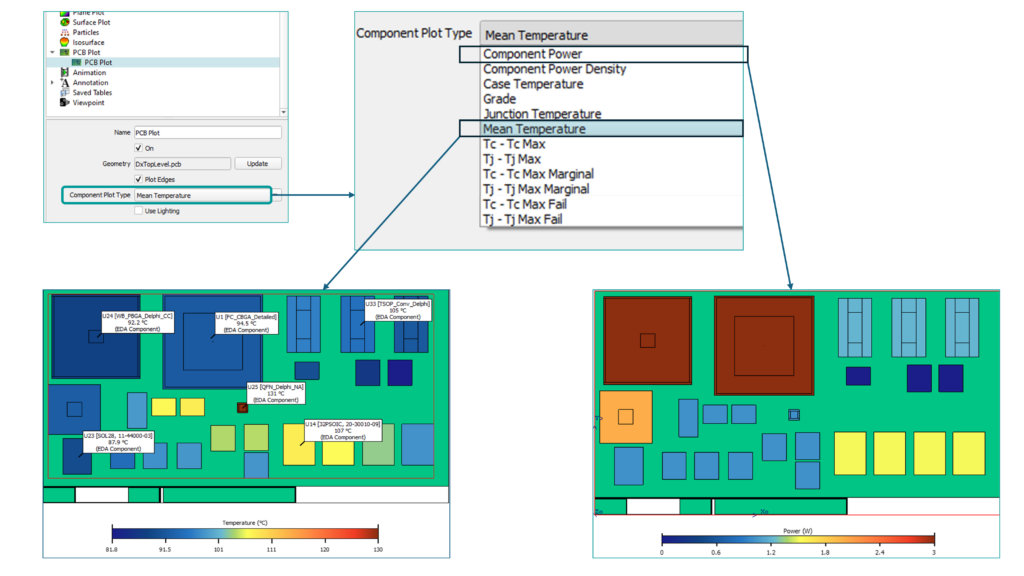
These new plots can be generated for PCB parts created using the Simcenter Flotherm EDA Bridge utility.

Improve PCB thermal analysis with easy component pass / fail / marginal identification

PCB’s can contain 100’s or 1000’s of components. Using tabular data and sorting by temperature results or powers is a typical approach. However, that may not easily indicate locations and groupings of components to understand thermal design issues. A quick visual identification of which components are passing or failing vs maximum allowable operating temperature is valuable to prioritize where to make remedial design changes.
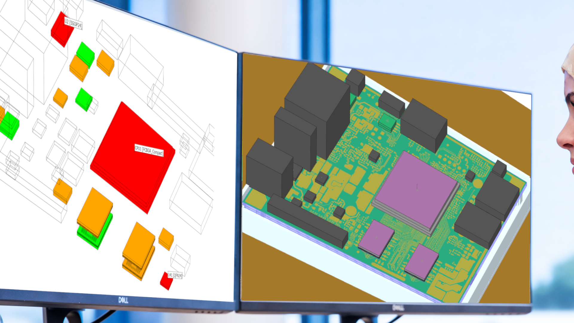
New PCB Plots provides the visualization solution. Users now can visualize grading of components by fail (red), marginal (amber), or pass (green) based on temperature compared to maximum allowable operating temperature for each component. The user sets the value for marginal variance above or below maximum allowable operating temperature.
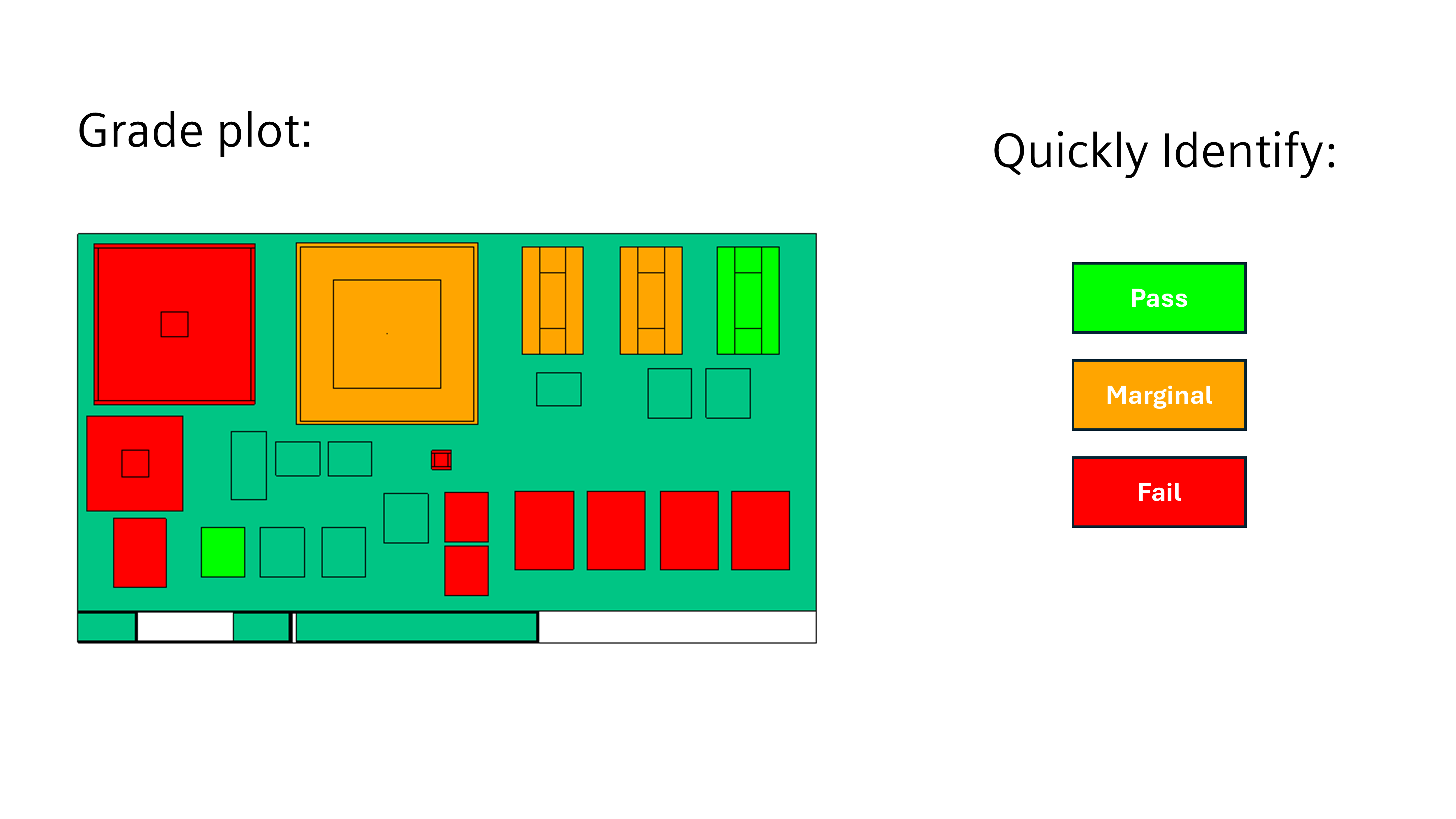
Users set the marginal temperature range in the in the Analyze Mode User Preferences
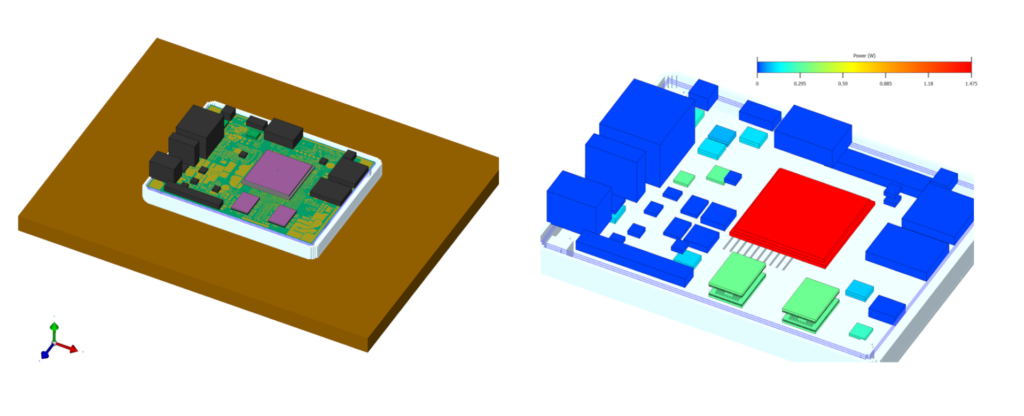
Below is a very simple example walked through for a PCB in an enclosure. The model contains a variety of components modeled in simple cuboid, two-resistor and detailed thermal model types.
1) Viewing the model and a PCB plot (new) of the power for each component


2) View pass / fail / marginal components with a grade plot

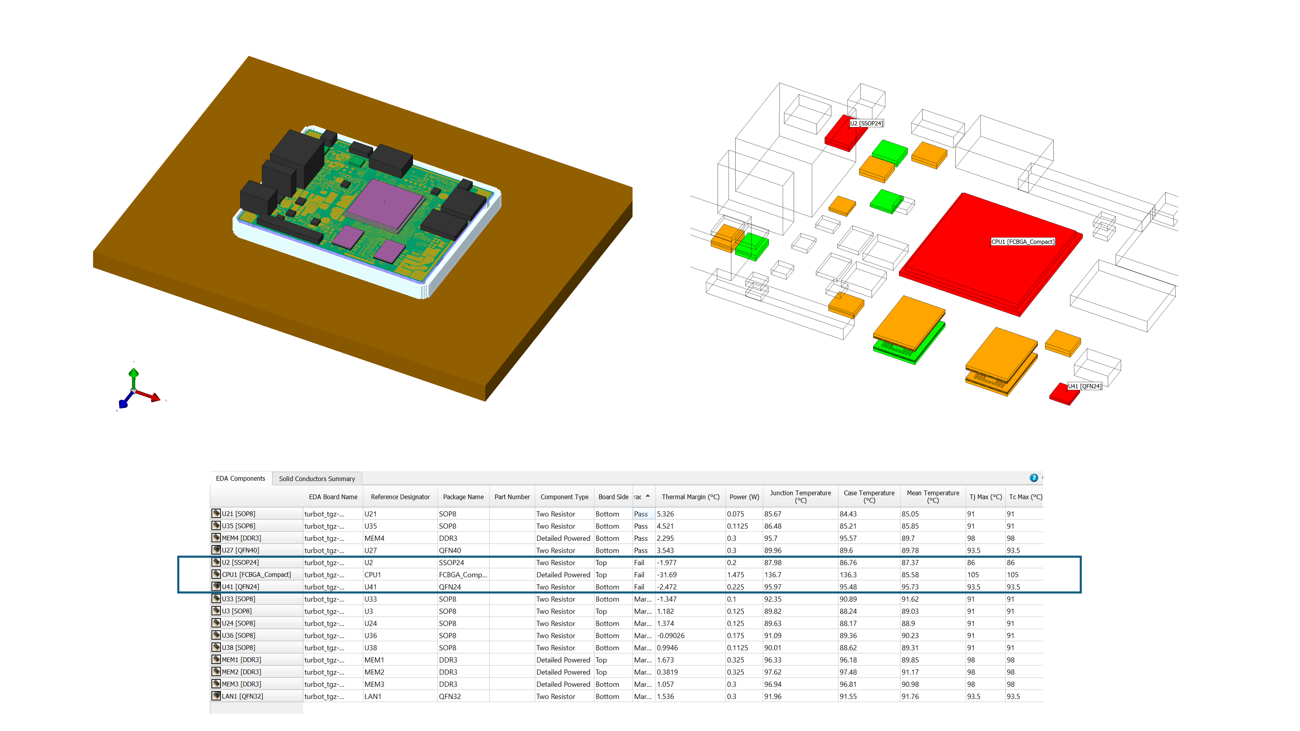
Clearly the centrally located GPU processor, an FPBGA, is failing and 2 other components in other locations. You can find these via tabular data as indicated at the base and sorting typically, however a PCB plot provides a fast visual way to understand where issues are arising.

3) View Tj – Tjmax for only failing components for more insight.
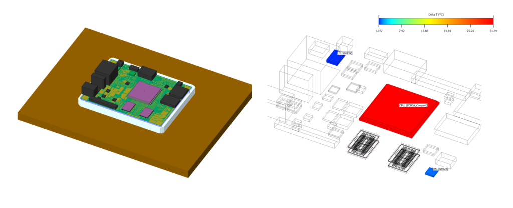
For this example, the CPU, is failing by the highest margin so is a good component to focus for initial remedial design actions.
4) Initial remedial design action 1: Add a heatsink and evaluate results
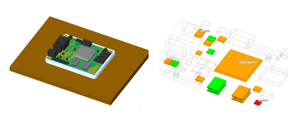
A standard aluminium pin fin heat sink is added onto the CPU. Using the same grade plot you can see quickly see that the CPU is no longer failing and temperatures are dropping. The design is improving.

5) Remedial design action 2: Replace the heatsink to enhance heat transfer
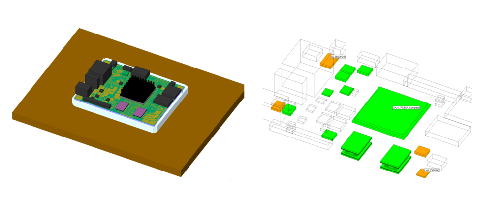
Replacing the heatsink with an anodized black heat sink increases radiative heat transfer. Most components are passing as seen in the grade plot and further decisions can be taken as necessary. This concludes the overview of using new PCB plots.
A note on simulation automation: You can also combine new PCB plots with scripting and automation available in Simcenter Flotherm. This functionality is supported within Floscript and GUI based macro recording. This means for large numbers of layouts or power variation studies for a given board, that you can automate analysis, parsing of results, and now also generate visual images of plots, such as the grade plot, that aids clearer communication to electronic and mechanical design team colleagues and management. Interested in PCB thermal analysis automation – see this recent webinar that covers scripting, macros, Python for Simcenter Flotherm and other tools.


Model the complexity

Heat flux reporting in Embeddable BCI-ROMs
3D CFD-ready reduced order models

Embeddable BCI-ROM technology enables creation of accurate reduced order thermal models of IC Packages that can be used in 3D CFD electronics cooling simulation studies, including transient studies. The accuracy of an Embeddable BCI-ROM is close to a detailed thermal model and crucially, all internal construction details of the package are not present so cannot be reverse engineered. This offers advantages in accurate modeling and IP protection to enable supply chain sharing. You can read more about Embeddable BCI-ROMs and BCI-ROM technology in this previous article.
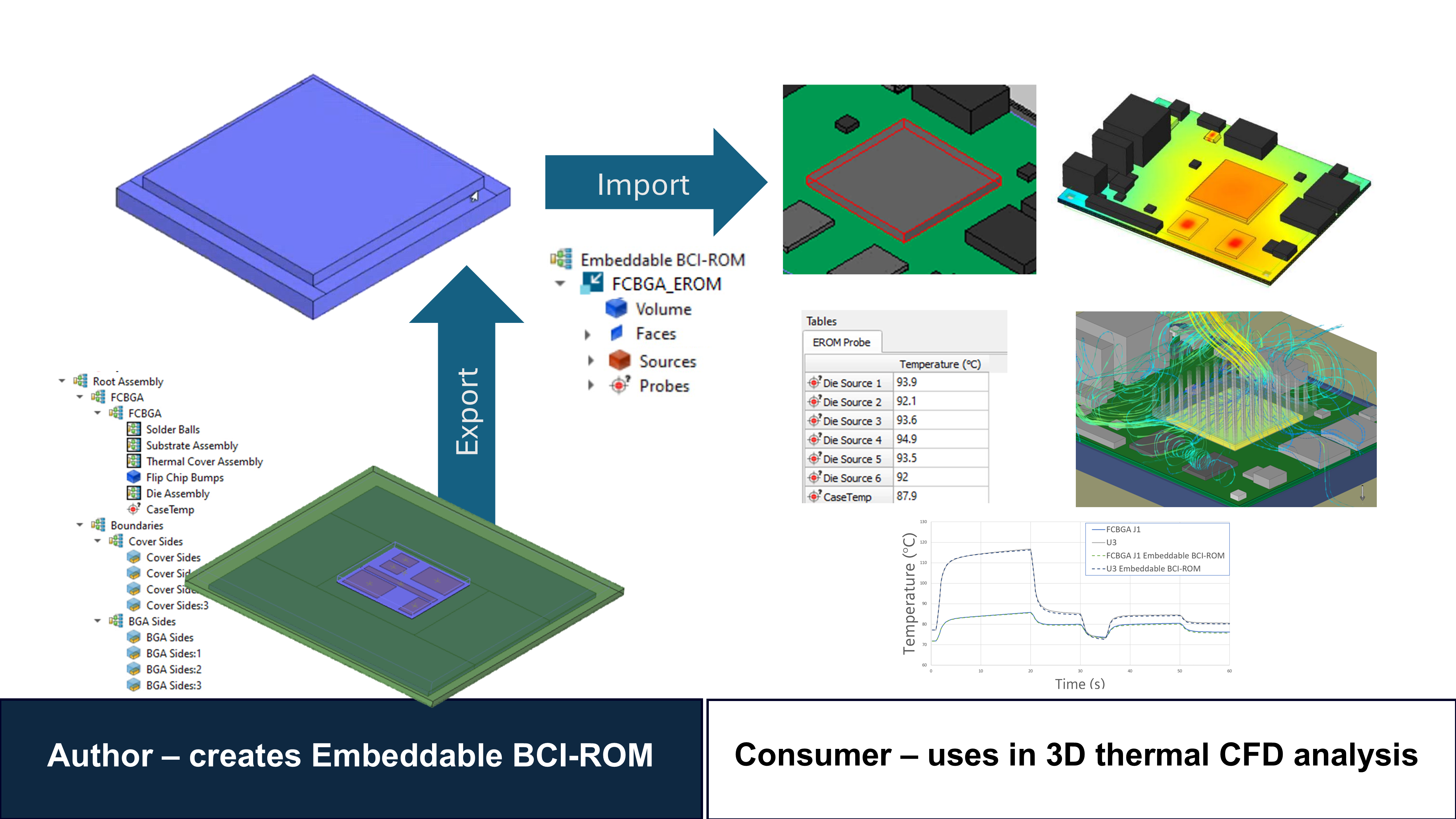

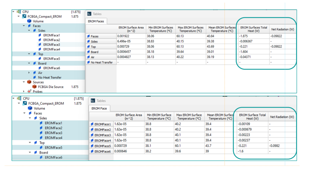
New in Simcenter Flotherm 2410, is the reporting of heat flux from the surfaces of an Embeddable BCI-ROM model. See the above blog for how surfaces are configured prior to export of the reduced order model. Heat flow splits in tables is now represented for all Embeddable BCI-ROM faces as shown below.

Thermal conductivity viewing of imported Material Map data

As a brief reminder, a Material Map is a computationally efficient and accurate method to represent material thermal property variations in PCB copper and layers, and for modeling complex IC package substrates and metalized dies. A Material Map file represents material properties as regions with sub-defined tiles that have set thermal conductivity, specific heat capacity and density values to fully represent material property variations. You can read more about Material Maps import in this previous article.
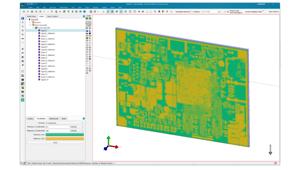
In Simcenter Flotherm 2410, you can now quickly view the Material Map values for thermal conductivity before solution. You can see the actual value for the tiles imported with a Material Map.
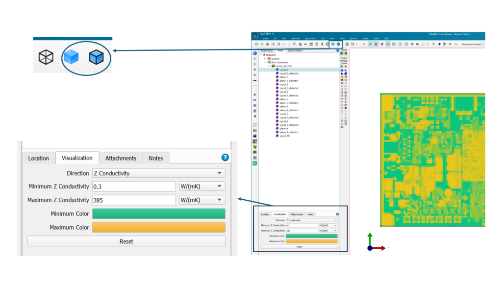
This is easily started by switching from wireframe to solid geometry view for a model with a Material Map. Users then leverage a new visualization tab in the Material Smart Part to:
- select the direction of conductivity
- set the maximum and minimum conductivity values (default values are read in from the file during import)
- select corresponding colors for min and max conductivity values to define a color map
You can reduce the range of conductivities shown to focus on viewing the most interesting areas of the Material Map. Anything outside of the defined range will be clipped so that it is white.
A note on security and encryption: For a Material Map exported from Calibre 3DThermal that has been encrypted, the thermal conductivity data is not visible which protects sensitive IP of the semiconductor organization it originates from. Calibre 3D Thermal is an thermal analysis tool for IC Designers, powered by Simcenter Flotherm solver technology.
For Simcenter Flotherm users interested in Material Map generation for PCB thermal analysis, I recommend this community article that describes converting an ODB++ file for a PCB into a Material Map via a Python script.

Download Simcenter Flotherm 2410 now

Download Simcenter Flotherm 2410 now from Support Center
(You can also download the latest Simcenter Flotherm Viewer 2410 version)
