KineoWorks step-by-step #3: working with trajectories

KineoWorksTM is a software component that automatically computes collision-free motion, solving complex path-planning problems in applications such as robotic collision-free trajectory optimization. In this series of articles, Etienne Ferré, Development Director of Kineo components, describes some of the key steps that you can easily implement to develop a sophisticated robotics simulation.
Part 3: Working with Trajectories
So far in this series, we have described processes for path planning and building a robot. This article takes a closer look at trajectories that describe the movement of a kinematic system over time. But first, a quick reminder about paths…
In KineoWorks, a path is described by a sequence of configurations. Elementary paths made of pairs of configurations are called direct paths.
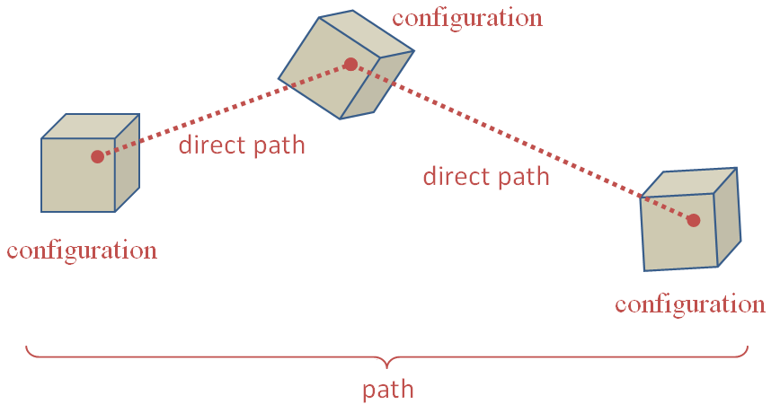
The purpose of a path is to connect a start configuration to a goal configuration in a configuration space. You can associate a configuration with any 1-dimensional position between 0.0 and the path length.
Path length meaning
Path length is usually the total distance along the path in a configuration space, but not always: it mainly depends on the path steering method. Most of the time, it is safe to assume that the lower the length is, the shorter the path is. This allows you to optimize paths, for instance, using length as a criterion. But length is not suitable for representing durations as it doesn’t describe where the system is at a given time. This is one limitation of using paths.
Path guarantee on continuity
A path is guaranteed to be continuous in position because losing position continuity would break the connection between the start and the goal configurations. However, there is no such guarantee of continuity of the derivative.
If you interpret the derivative of a path as velocity, you are not guaranteed continuous velocity. Typically, a sequence of direct paths, with a linear steering method, going in different directions will jump from a constant velocity in one direction to a constant velocity in another direction. You would not be able to run such a path on a real system which requires at least a continuous velocity. This is a second limitation of using paths.
With a linear steering method, the velocity on the y axis jumps from a positive value to a negative value
Executing a path on a real system
Despite these limitations, as a solution to a path planning problem, a path does the job: it connects start and goal configurations. A path is all we need to make this connection in the valid configuration space. However, as seen above, a path in general does not describe how the system should move over time, because it does not take into account maximum velocity, maximum acceleration, continuity constraints and other parameters of the real system.
A solution to this problem is to use specific velocity profiles such as the trapezoidal velocity profile. Such profiles allow a path to be followed exactly while guaranteeing a continuous velocity at one cost: the velocity must be null at waypoints when the direction changes. Such profiles can be managed by a 3rd party robot controller (requiring only path configurations as input) or they can be simulated with the corresponding steering method. The trapezoidal steering method is an example where the length of a path is no longer a distance because it simulates motion over time.
The solution above is not always satisfactory because:
- Stopping at each waypoint can slow the overall motion significantly
- The trapezoidal steering method is unsuitable for systems that require continuous acceleration
- Even with continuous acceleration, the relation between path length and motion time is obscured
- You will not benefit from collision-free motion planning in KineoWorks if you select a 3rd party robot controller to compute the real motion
So when it comes to simulating system motion, paths are not the best choice. This is why we introduced the concept of a trajectory.
Introduction to Trajectories
A trajectory fully describes the movement of a real system, in other words, the position of the system over time. While paths are parameterized with respect to distance, trajectories are parameterized with respect to time. The conventional unit of trajectory duration is the second. A trajectory still follows a path in a spatial sense, but adds information to it: two different trajectories can follow the same path with different timings. For each time interval, you can get the position of the system’s active axes, and also their velocity, acceleration and jerk (derivative of acceleration). In addition you can get the energy consumed by the system when it runs the trajectory.
The CkwsTrajectory class is the most abstract interface for a trajectory. It provides enough information to run and evaluate trajectories obtained through other API functions (see later)..
Playing a trajectory
Playing a trajectory is similar to playing a path. But while paths explore configurations as a function of distance along the path, trajectories are more natural – they explore how configurations evolve as a function of time. So in the example code below, both trajectory duration and CkitTime are measured in seconds..
Here is an example of how you can play a trajectory:
if(m_trajectory && m_trajectory->isValid())
{
   CkttDisplay::message("Playing trajectory...");
   CkwsConfig config(m_trajectory->device());
   CkitTime    timer;
   timer.start();
   double t = 0.;
   while(t <= m_trajectory->duration())
   {
      if(KD_OK == m_trajectory->getConfigAtTime(t, config))
      {
         setCurrentConfig(config);
      }
      t = timer.elapsedTime();
   }
   if(KD_OK == m_trajectory->getConfigAtTime(m_trajectory->duration(), config))
   {
      setCurrentConfig(config);
   }
   CkttDisplay::message("Ready");
}
Testing a trajectory for collision
You can test a trajectory for collisions using a trajectory tester. This code illustrates the simplest way to do this:
CkwsTrajectoryTesterShPtr trajectoryTester = CkwsTrajectoryTester::create();
bool doesCollide = false;
ktStatus status = trajectoryTester->collisionTest(trajectory, doesCollide);
if(status.succeeded())
{
   std::cout << "the trajectory is" << (doesCollide ? "" : " not") << " colliding" << std::endl;
}
else
{
   std::cout << "collision test failed : " << status.description() << std::endl;
}
For maximum control over the collision test, you can customize validation parameters and other properties. In addition, other overloads of CkwsTrajectoryTester::collisionTest allow you to test for collisions in a parent configuration space.
Transforming a Path into a Trajectory
It’s not always possible to transform the output of a path-planner into a trajectory that follows the precise path while avoiding collisions. For example, a spline trajectory cannot follow a straight line path.
This is why we introduced the concept of a motion planner. This is an object that enables you to transform a (collision-free) path into a (collision-free) trajectory. Even if it is possible to follow the original path with a robot controller trajectory, motion planners provide an abstract API to transform a path into a trajectory.
There is a motion planner for each of the two implementations of trajectory in KineoWorks:
- the robot controller motion planner
- the cubic spline motion planner
Here we consider the cubic spline motion planner. You can assign a cubic spline motion planner to a robot using the following code:
robot->motionPlanner(CkwsCubicSplineMotionPlanner::create());You can then use the robot motion planner to make a trajectory (with m_trajectory as an output parameter):
  CkitParameterMapShPtr parameters = CkitParameterMap::create();
  parameters->setBool("com.siemens.kineo.motion-planner.trajectories-must-be-valid", true);
  parameters->setBool("com.siemens.kineo.cubic-spline-motion-planner.is-constrained-trajectory", false);
  robot()->motionPlanner()->makeTrajectory(m_path, parameters, m_trajectory);
The call to makeTrajectory also takes a parameter map as input. You can find details of possible parameters in the parent class documentation and the specific motion planner class documentation.
You may choose to replace the cubic spline motion planner in the tutorial with a robot controller motion planner. In this case, you will need to load the robot controller simulator (RCS module) and create an RRS robot to pass to the create method.
Optimizing Trajectories
Using KineoWorks Trajectory Optimizer
You can optimize mutable trajectories using a trajectory optimizer.
In this tutorial, the paths that you have transformed into trajectories using a motion planner are not yet optimal – they can be slow to play. In order to improve the trajectories, you should use a trajectory optimizer.
Create and configure the trajectory optimizer with this code:
// Create and configure the trajectory optimizer
CkwsTrajectoryOptimizerShPtr optimizer = CkwsTrajectoryOptimizer::create();
optimizer->inputTrajectories(std::vector<CkwsMutableTrajectoryConstShPtr>(1, m_trajectory));
optimizer->optimizationType(CkwsTrajectoryOptimizer::CYCLE_TIME);
optimizer->iterationCount(5);
CkitParameterMapShPtr inputParams = CkitParameterMap::create();
inputParams->setDouble("com.kineocam.genetic-optimizer.standard-deviation", 0.01);
You can set some parameters directly through the CkwsTrajectoryOptimizer API, whereas others must be set in the parameter map. You can find details of possible parameters in the class documentation.
The operation is executed with a blocking call, then the output trajectory is retrieved:
CkitParameterMapShPtr outputParams = CkitParameterMap::create();
optimizer->operate(inputParams, outputParams);
CkttDisplay::removeTrajectory(m_trajectory);
m_trajectory = optimizer->outputTrajectory();
The optimization can take up to several minutes. Optimization duration and output quality depend on the parameters. For instance, you can change the iteration count to see how it affects the optimization duration and the output quality.
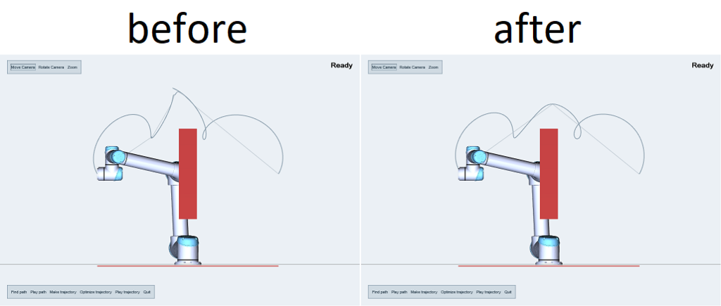
In this example, the optimized trajectory appears to match the original quite well, but if you look closely, the number of waypoints has been reduced and the trajectory is smoother. As a result, the optimized trajectory will play much faster compared to the original, which is what we would expect as duration was the criterion for optimization. A fast-to-play long path will be preferred over a slow-to-play short path, and we may be in a local optimum that prevents the trajectory getting shorter.
In the the final part of this series, we’ll take a closer look at how you can easily build a pick & place operation.