D-Cubed 3D Components release highlights
D-Cubed 3D components are integrated by software developers to add 3D modeling capabilities to CAD/CAM/CAE and AEC software applications. These applications are used to design, analyse, visualize, and manufacture products from consumer goods to aircraft engines and commercial buildings.
D-Cubed 3D DCM version 60.0
D-Cubed 3D DCM (3D Dimensional Constraint Manager) is a geometric constraint solving software component. Supporting a wide range of geometries, dimensions and constraints, 3D DCM enables 3D parametric sketching, part shape control using direct modeling, assembly part positioning and kinematic motion simulation. Key enhancements introduced in version 60.0 of D-Cubed 3D DCM are described below.
Constrain to the planar component of a circle or torus
New functionality enables a dimension or coincident constraint to apply directly between a point and the planar component of a circle or torus. Previously, application developers would need to construct additional geometry to support this constraint.
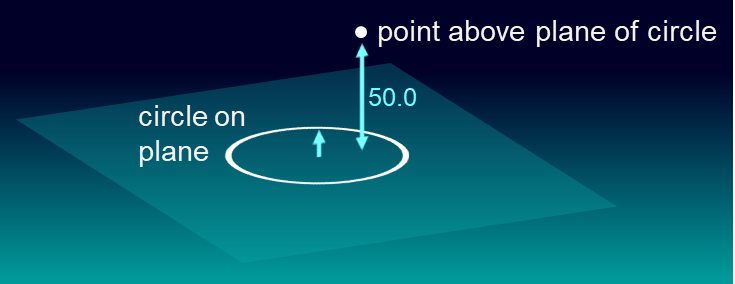
Distance applied between point and plane of circle
Sets with transforms
3D DCM supports the grouping of geometry into a set, which can be used to define a rigid 3D part. This provides an easy method for positioning a 3D part using geometric constraints, while ensuring the constraints will not affect the part’s shape. To mitigate against any potential loss of solving accuracy when positioning sets over large distances, the latest version enables applications to specify the transformation of the set in which geometry has been grouped, resulting in potential performance improvements.
Under-defined degrees of freedom of a set
When dimensions and constraints are used to position 3D parts in assemblies, they remove the parts’ degrees of freedom. In the absence of any positioning constraints, 3D parts have no unique location along X, Y and Z axes, and no unique rotation about those same axes. This usually results in 6 degrees of freedom for any given part, though there are exceptions. For example, a rivet has intrinsic rotational symmetry, so only 5 degrees of freedom need to be removed before its position is uniquely defined. Understanding the degrees of freedom of a 3D part helps designers to apply suitable dimensions and constraints that uniquely define the part’s location.
3D DCM provides comprehensive diagnoses on degrees of freedom and version 60 provides enhanced feedback about the degrees of freedom of an under-defined part in cases where the geometry has symmetry.
D-Cubed CDM version 60.0
D-Cubed CDM (Collision Detection Manager) is a software component that offers collision detection and clearance distance measurement for solid, surface, wireframe and point cloud models. It supports accurate, tolerant and faceted geometry. Used in assembly, mechanism, machining and measurement simulation environments, CDM offers a range of algorithms to interactively detect collisions and compute clearances, even on large, complex assemblies. Performance is particularly excellent for common operations, such as repeated computations on models that are in motion. CDM is compatible with most applications, being independent of any modeler or model format. Key enhancements introduced in version 60.0 of D-Cubed CDM are described below.
Direct support for helical curves
Applications can now add helical curves direct to the CDM, enabling more efficient analysis of familiar structures like screw threads. Previously, such curves would be added to the CDM as general parametric curves, requiring the CDM to use call-back functions with the application to evaluate their position and shape. The new functionality improves reliability and performance using the direct representation for this geometry.
Closest approach functionality
Closest approach functionality allows the application to enquire all the face-face closest approach solutions between two bodies within a given capping distance. The functionality has been extended to optionally return solutions on face boundaries.
SVG debug output
New functionality enables a CDM-based application to obtain debugging data in SVG format which can be viewed by most web browsers.
D-Cubed HLM version 60.0
D-Cubed HLM (Hidden Line Manager)) is a software component that provides applications with a fast hidden line computation capability. HLM is optimized for solid, surface and wireframe models, with support for accurate, tolerant and faceted geometry. HLM is compatible with most applications, being independent of modeler or model format. HLM accurately computes hidden line views, engineering drawings and technical illustrations of parts and assemblies with exceptional performance, reliability and functionality. Key enhancements introduced in version 60.0 of D-Cubed HLM are described below.
Direct support for helical curves
In the same way as for CDM (see above), applications can add helical curves direct to the HLM, removing the need to use call-back functions with the application to evaluate the curves’ position and shape, therefore improving reliability and performance.
SVG debug output
As for CDM, new functionality enables the application to output debugging data in SVG format which can be viewed by most web browsers.
D-Cubed AEM version 60.0
D-Cubed AEM (Assembly Engineering Manager) is a software component that enables applications to simulate the motion of assemblies and mechanisms. It accounts for the mass properties of parts, the motion caused by a range of engineering forces and devices and the interaction of parts as they collide and transmit motion to each other. Key enhancements introduced in version 60.0 of D-Cubed AEM are described below.
Enhancements to contact computations
AEM has pioneered motion simulations in environments where accurate solid models, not faceted approximations, come into contact and push each other around. This is a more sophisticated process than operating on faceted parts, as there are many more geometry types and configurations involved in computing contact-based motion on full solid parts. The benefits are substantial, including the direct simulation of motion on parts with a geometric accuracy that is suitable for engineering applications, rather than visualization or entertainment. The latest release sees ongoing improvements to the algorithms used to calculate the contacts when bodies collide.

