KineoWorks step-by-step #2: building your robot with Kwik

KineoWorks is a software component that automatically computes collision-free motion by solving complex path-planning problems in applications such as robotic collision-free trajectory optimization. In this series of articles, Etienne Ferré, Development Director of Kineo components, describes some of the key steps that are easily implemented to develop a sophisticated robotics simulation. In part 1 of our series, we discussed path planning. This article explains how you can easily develop a virtual robot.
Part 2: Building your robot with Kwik
KineoWorks comes with a very complete and powerful API for creating robots and other kinds of kinematic systems. However, for complex kinematics, manipulating geometric features using an API can be a very difficult and error-prone task due to the lack of immediate feedback. For this reason, Kineo offers a much more intuitive and rewarding way to model kinematic systems. It’s an interactive graphical editor called Kwik (KineoWorks Interactive Kinematics) and as the name suggests – it’s the fast way to build your robot.
Workflow
The following diagram summarizes the workflow for robot modeling. You can use a similar workflow for modeling other kinds of systems.
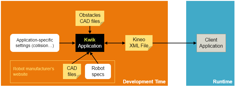
Robot Modeling Steps
Here is a step-by-step procedure for modeling a robot with Kwik:
- Gather technical data from the robot manufacturer’s website:
- CAD files for robot geometry
- Technical specifications (dimensions, axis bounds, axis directions, …)
- Use Kwik to model the kinematic chain, then import CAD data and attach CAD to kinematics
- Import any geometries you need to represent the operating environment
- Model any auxilliary systems (external axis, articulated tool, …)
- Perform additional application-specific setup such as collision detection
- Export your data as a Kineo XML file
- Make this file a resource of your application
- Use the Kineo API to import the data into your application
You can use the full KineoWorks API to perform any additional setup that Kwik does not currently support.
Example: Modeling a 6-axis ABB Robot
This section illustrates the complete modeling of the ABB IRB 2600 1.65 robot. You can use the same instructions to model any other standard 6-axis robot. With minor changes, you can also model any other kind of kinematic system.
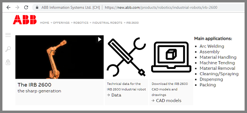
Downloading Data from the Robot Manufacturer’s Website
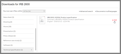
Most robot manufacturers publish robot specifications and CAD models on their website. You can find the ABB IRC 2600 robot product page on the web, which provides links to technical data and CAD models:
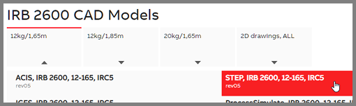
Kwik imports geometrical data in many formats including JT, STL, VRML, STEP, CATIA V5. Select your choice of supported format. For instance, you might choose the STEP format:
You should also download the technical specifications PDF:
Importing CAD Data into Kwik
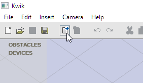
First, start Kwik.
In the toolbar, click the Import icon (or choose File > Import):
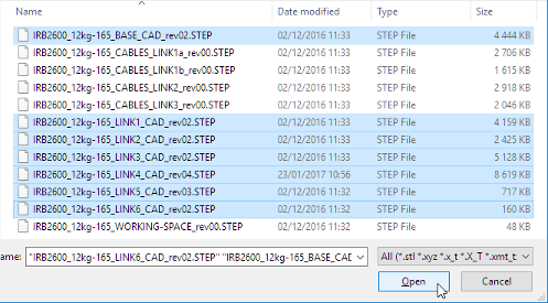
From the unzipped archive that contains the downloaded CAD data, select relevant geometry. In this example, import the base of the robot and its 6 axes. You will not require the working space and flexible cables:
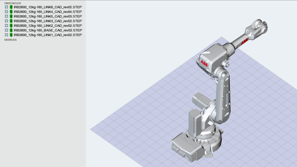
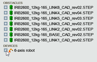
Imported geometries are listed under Obstacles and displayed in the 3D view:
Modeling Kinematics
From the Insert menu, choose 6-axis robot:
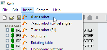
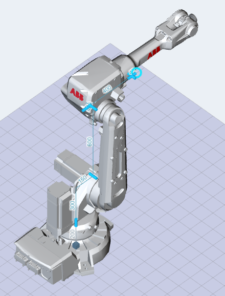
This creates a template for standard 6-axis robot kinematics. Joints are displayed as blue cylinders and lines in the 3D view:
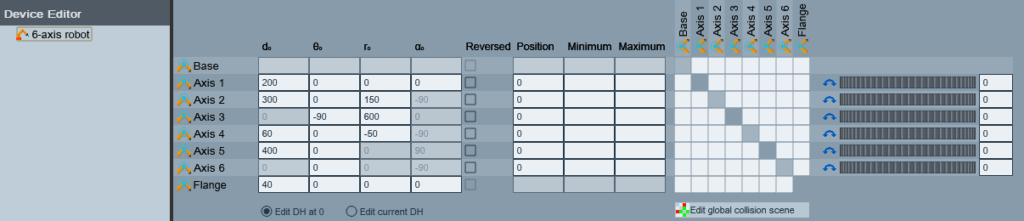
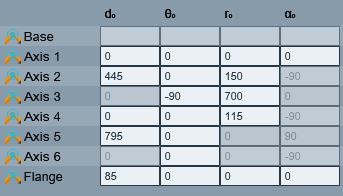
The template dimensions are arbitrary so you must edit them to match your particular robot. To edit joint positions, first select the robot in the Device Editor. The Device Editor displays data for all robot axes in a single place:
You will find the correct dimensions in the specifications PDF:
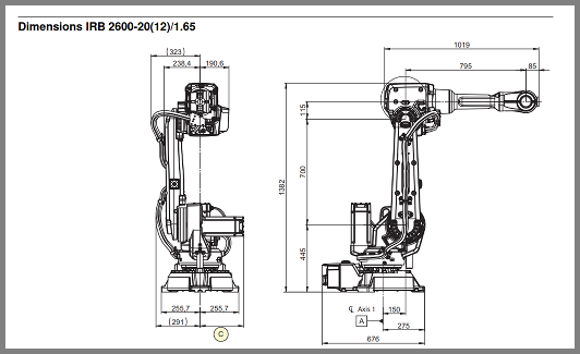
Just copy them to the Device Editor:
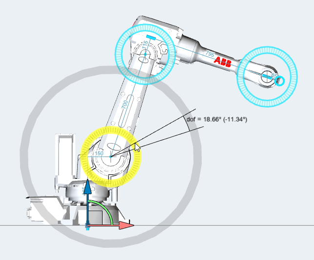
You can perform a quick visual check to verify that the values are correct. Choose Camera > Change orientation to > Front (or hit F). You should see that the joints align well with the geometry:
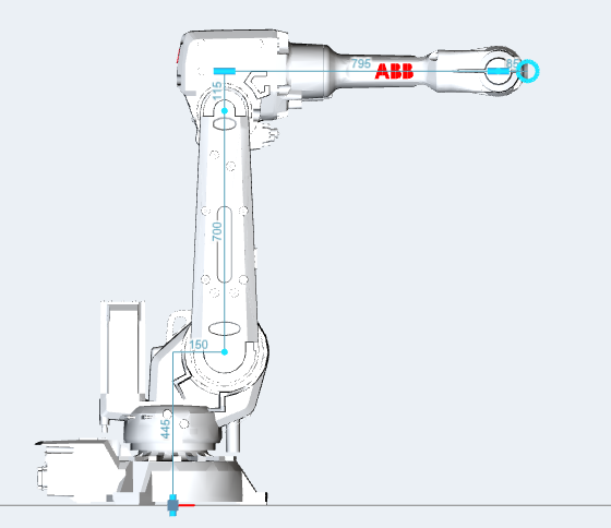
You can also choose Camera > Change orientation to > Left (or hit L) to check that the joints are at the same depth as the geometry.
Attaching Geometry to Axes
The imported geometries and kinematics model are currently independent from each other so you need to link them.
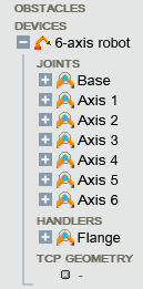
Click the + button next to the robot to display its axes:
Drag each imported geometry from the Obstacles section to its corresponding axis (BASE -> Base, LINK1 -> Axis 1, etc.)
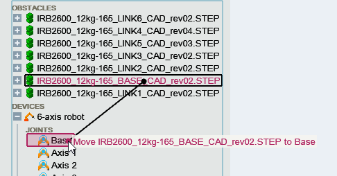
Your document should now look like this:
You can verify the correct linkage of geometries and axes visually by jogging the degrees of freedom of the robot.
Exporting the Robot
Once a robot has been modeled in Kwik, you can export (i.e. serialize) it to an XML file that you can package as a resource of your application and import using the KineoWorks API.
Firstly, Select the robot to export and click the Export button in the toolbar (or choose File > Export). Secondly, Choose a name for the file. You can use .kwd for devices (including systems and robots), .kws for systems (including robots) and .kwr for robots. Select .kwr in order to make it clear that the XML file describes a robot and not some other device.
The file is written to disk. At the same time, source code is copied to the system clipboard which you can paste into your code editor:
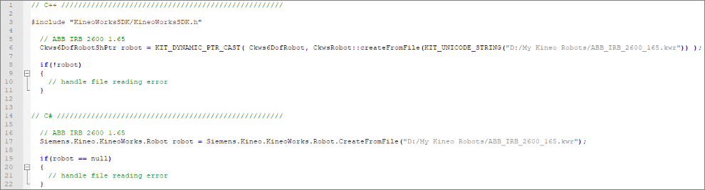
The source code enables you to retrieve the robot as an object using the KineoWorks C++ or C# API.
In part 3 of our series, we’ll take a closer look at how you can control the motion of the robot and explore the difference between a path and a trajectory.