Making Sure We Got It Right: CMM Inspection Programming for the Quadcopter Mold
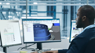
We’re nearing the completion of our tour through the Digital Machine Shop. My name is John Zhang, and I am a Dimensional Management Consultant at Siemens Digital Industries Software. This post looks at the inspection process, and I will discuss how the same digital thread we’ve followed through the design and manufacturing of the quadcopter mold continues seamlessly into another critical operation – part inspection on a coordinate measuring machine (CMM).
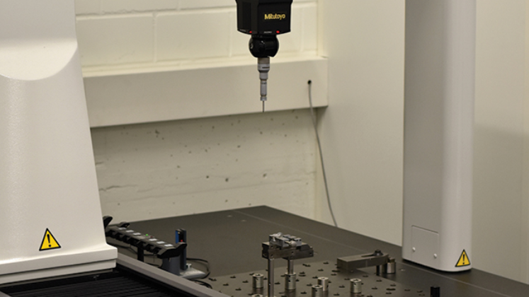
Specifically, I’ll show how the Siemens solution, NX CMM Inspection Programming, was used in this project to program a Renishaw Equator machine to verify the dimensions of the mold core. As with the previous blog posts in this Digital Machine Shop series, you’ll see the advantages of the Digital Twin approach, in this case for accelerating and optimizing CMM inspection programming. These include:
- Automating CMM programming by using the PMI data attached to 3D digital models
- Validating machine moves using a digital twin of the CMM machine
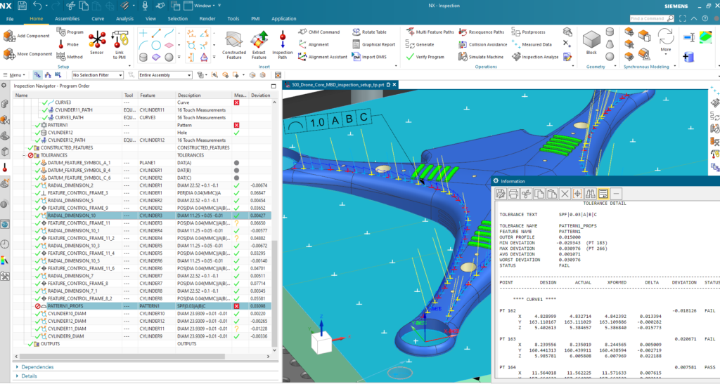
- Analyzing and visualizing CMM data on the 3D model to close the loop between design and production
These benefits are the result of connecting the inspection department with the digital thread that unifies the end-to-end production process. This connectivity allows the quality inspection engineers to reuse 3D model data, similar to the way CAM programmers use CAD data to accelerate toolpath creation. Traditionally, inspection is not integrated in this way. Often, CMM programmers work from 2D drawings and use stand alone applications, requiring a programmer to manually augment the information on drawings with dimensional, shape and position tolerances. It also requires a physical part and consumes a lot of valuable CMM time.
Associativity between the CAD, CAM and CMM applications in NX not only eliminates these obstacles. It gives you the ability to digitally transfer design intent all the way to production, and to quickly adapt inspection programs in case of design changes.
The Digital Journey of the Modern Machine Shop
Learn to make manufacturing lead time an asset and embark on a path to profitability with the digital machine shop in our eBook.
CMM programming automation via PMI
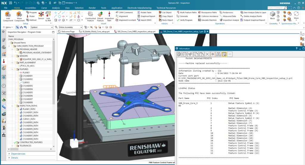
For the quadcopter project, I imported the CAD model of the mold into NX CMM Inspection Programming software. In addition to part geometry, the data I received included product and manufacturing information (PMI) such as geometric dimensions and tolerances (GD&T), 3D annotation and dimensions, surface finish and material specifications.
The software used this information to automatically define the probing path needed to inspect the mold core. There was no need for me to re-enter any information by hand. I was also able to apply some of my own standard inspection path methods to further automate the programming process for this part.
I sped up the programming using the automated CMM inspection approach in NX compared to the traditional methods. Some of our customers are finding CMM programming times have dropped by as much as 80% after switching to the automated, NX-based solution.
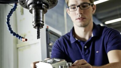
My inspection of this mold core used a touch probe, a tried-and-true inspection method well suited to this fairly simple part. NX CMM Inspection Programming also supports newer methods, including non-tactile measuring probes such as lasers scanners and optical sensors, as well as on-machine probing.
Simulation and results analysis
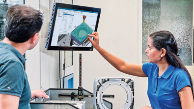
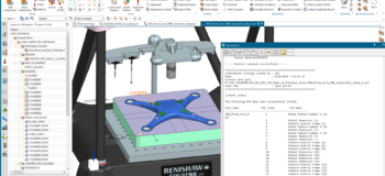
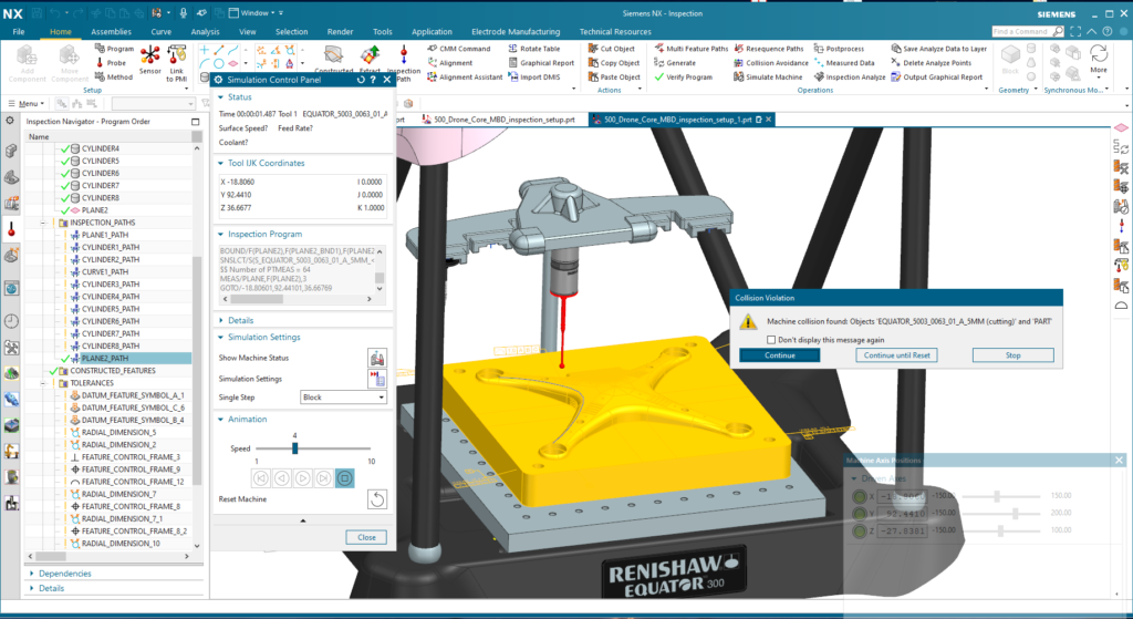
NX CMM Inspection Programming software generate the machine instructions for the CMM equipment, either in industry-standard DMIS format, or specific to a particular machine, which was the option I chose knowing I’d be using a Renishaw Equator. Before I sent the program to the shop floor, I simulated the probing path in NX to check for interferences and other motion issues. To accurately simulate the process, I used an exact digital replica of the CMM with the same kinematics as the real machine. This step helped me avoid (costly) problems such as a probe hitting the part, and also to verify that all features were reachable and that machine limits would not be exceeded.
Integrating the inspection process within a Digital Machine Shop makes the results of the inspection process much more valuable than simply verifying that a part meets its design specifications. It lets you feed the results from the CMM machine back into NX, where it can be compared to the original 3D CAD model. A comparison of the “as-built” with “as-designed” versions of the part closes the loop between design and manufacturing.
Model-based quality
I mentioned earlier how my use of the mold core’s PMI data accelerated CMM inspection programming. The success of this approach relied on having accurate GD&T data, which was the case for me with the mold core. But CAD models, like drawings, can have errors in GD&T. Had this been the case with the PMI data I used, it still would have accelerated CMM inspection programming but the probing paths or tolerances would not have been accurate.
Siemens has introduced a Model-Based Quality (MBQ) approach that ensures the integrity and interoperability of PMI data. This is a comprehensive solution that digitally connects all those who require accurate dimensional data – design engineers, manufacturing engineers, tooling and fixture engineers, and quality engineers.
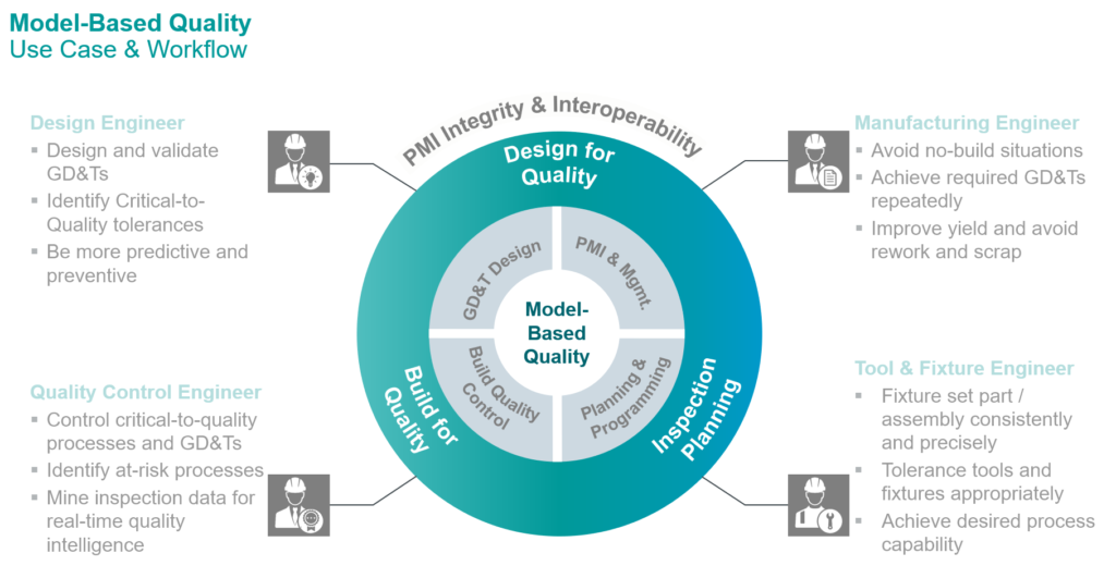
Model-Based Quality starts with the creation of a 3D CAD model (the Digital Twin of the product). After the model is created, NX Model Based Definition eases the process of capturing manufacturing information and associating it with 3D geometry (thus enriching the Digital Twin of the product). This modern solution eliminates syntactical, semantic and mathematical errors in GD&T, which are frequent causes of downstream problems with PMI.
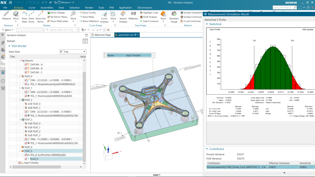
NX VSA, an application for Variaiton Simulation Analysis, is part of the MBQ portfolio that uses the GD&T as the basis for simulations of GD&T fabricatons and assembly processes, predicting the amount of dimensional variation in a batch of finished products. This is where you can see if tolerance stack-ups will cause problems, and remedy them before you have to scrap or recall actual products and/or parts. The software shows you the causes of variation to help with improving product and process design. It also identifies which PMIs are critical to quality – helpful information for CMM programmers and quality assurance engineers.
The benefits of closing the quality loop using MBQ are extensive. To learn more about this approach to achieving profitable quality, please take a quick look at this short MBQ overview video.
Read the first blog in our digital machine shop series here, catch up on the previous blog on additive manufacturing here, and read the final blog in the series on shop floor connectivity here.
Precision part manufacturer integrates NX solutions to digitalize the entire production operation
Programming help C-Mill improve product quality and cut equipment downtime by 80 percent.