Topology Optimization Shape Constraints | NX Tips and Tricks
Welcome to another instalment of our Tips and Trick series! As you hopefully know by now, we bring you these to provide useful information from our NX continuous release strategy. Our aim is always to improve your overall design workflow, and with any luck, these tips and tricks support that goal! In this entry we’ll be looking at how to utilize shape constraints with Topology Optimization to achieve optimized results that are more in line with different types of manufacturing processes.
Let’s get started!
Optimized Shape, but no constraints
In our example, we’re going to start by looking at an optimized part, but without any constraints. As you can see in our model, this specific part has several crevices and overhangs involved, making this part difficult to cast and manufacture. This is something we want to pay attention to when building out our model further, as this can hinder and slow down the design and manufacturing process. Let’s look at making some design changes to our model. This way, we can ensure it can be more easily manufactured using traditional methods.
Fill from direction
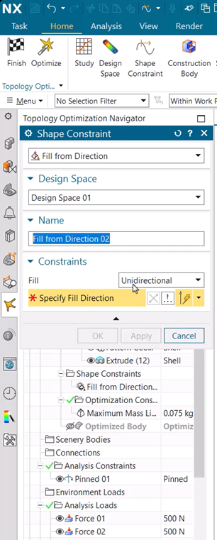
Under ‘shape constraint’ you can find where to add ‘fill from direction’. In our example, this is what we’re going to add. This option will ensure that the model is built up from the base and the model wouldn’t be locked if it were to be cast. Remember here to select ‘unidirectional’ and then the vector that you want your model to be built up from.
Using our video as an example, once the part has finished running, you are able to see how the body has changed. For instance, with the addition of a shape constraint, the model still resembles your original, but no longer contains overhangs or crevices. With the model now having tall walls, it’s much more practical to cast and be sent for manufacture.
Bidirectional from a plane
Within NX there are several different options when it comes to deciding the shape of the model. Again, in our video, you can see that this third example has a different design from the previous two. This has been achieved by selecting ‘bidirectional’ instead of ‘unidirectional’. We have then selected a plane that has been placed midway through the body of our model. This enables the part to have a more internalized structure but maintaining the omission of crevices or overhangs to help with ease when casting.
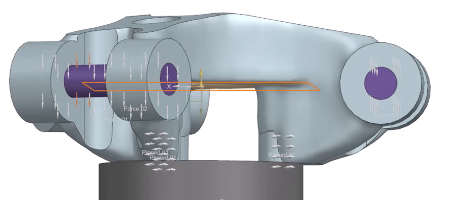
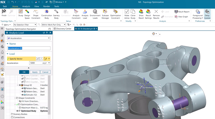
Acceleration load
When creating any model or part within NX, it’s essential to remember what function your model will have in the real world. This part that we’re looking at in particular would be used to hold a load on its linkages, and potentially have something that could crash into it at force. Due to this, we need to ensure that our part could sustain that very possible impact. We can check this by adding an ‘acceleration load’ to the model. This can be found under ‘analysis load’. This part is entirely up to you in terms of where you choose your potential impact to be from, but in this instance, let’s say it’s coming from the X direction. Once you’ve chosen that, simply optimize our design and view your results. Referring to our example, you can see how the design has changed to accommodate for this sudden acceleration. Material has been removed from the front of the model and then added to the back to keep the model from deforming.
Continue your journey with NX
And that’s a wrap on utilizing shape constraints! We hope you have found this useful, and it helps improve your workflow. Please stay tuned for the next entry, as we continue to help your designs reach their optimum potential.