NX | Tips and Tricks | Algorithmic Text Modeling
Our latest NX™ software Tips and Tricks video demonstrates a useful new algorithmic modeling tool for controlling offset regions.
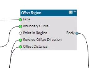
Released in December 2023, the Offset Region node is a versatile addition to the Logic Editor with five inputs to connect with other nodes in your logic rules. We’ll show you how to use it with the Text On Face node to create embossed or indented text on a body.
Introduction to Algorithmic Modeling
The workflow we explain here follows on from our previous Tips and Tricks post about Algorithmic Modeling.
It’s worth reading that blog first to familiarize yourself with the dataset and the design process. It’s also a great introduction to creating algorithmic features using the intuitive visual programming in NX’s Logic Editor.
But if you’re short on time, here’s a quick summary:
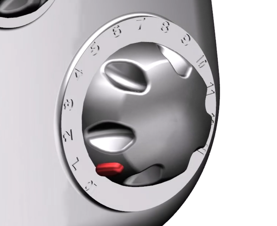
- The model is a shower unit with two control dials
- We used algorithmic modeling to add display text around the flow control dial
- The feature dynamically updates so we can quickly change the text without manual re-modeling
The new Offset Region node
In the previous blog, we embossed the text on the shower unit with the Extrude command. This is quite efficient because using Extrude on the algorithmic feature affects all of the text at once – you don’t have to select and Extrude each piece of text individually.
The Offset Region node, however, allows an even better approach. We can now incorporate the embossed effect within the algorithmic feature itself by adding the new node to our existing rule.
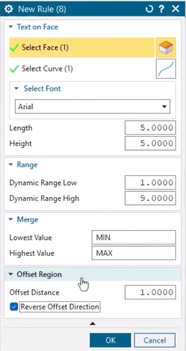
First we need to define the Face, the Boundary curve and the Offset Distance inputs.
- The face is the same as for the rest of the rule, so we simply link that to the existing Select Face node
- A flattened list from Text on Face‘s Curves output provides the inner and outer boundaries of the text
- We can set the offset distance with a numerical value input of our choice
After inputting an offset distance, you can preview the offset in the Graphics Window.
You can also use Reverse Offset Direction with a Boolean input – in this case, that lets us choose between embossed and indented text.
Dynamic updates
As we showed in the previous blog, one benefit of algorithmic features is that you can quickly make significant changes by simply tweaking a few parameters.
You can do this straight from the Part Navigator by right-clicking an algorithmic feature and selecting Edit Parameters.
Adding the Offset Region node to our model has given us two more parameters with which we can control the feature – Offset Distance and Reverse Offset Direction.
The latter lets us switch between embossed and indented text by simply checking or unchecking a box.
Whatever parameter you change, you can see the entire algorithmic feature dynamically update in the Graphics Window.
Watch the Tips & Tricks video
It’s called visual programming for a reason, so the best way to understand the power of algorithmic modeling in NX is to watch the video!
And remember, you can save Logic Editor rules to the Reuse Library to accelerate design time even more when you and your colleagues work on future projects.


Comments
Leave a Reply
You must be logged in to post a comment.
Cool breakdown of algorithmic text modeling—practical tips like adjusting parameters and evaluating outputs make complex concepts more approachable while stressing iterative refinement and evaluation. Tools that help ask ai targeted questions can accelerate learning these techniques and clarify tricky parts of model tuning or prompt design. Exploring how different token constraints or sampling strategies affect results becomes easier when you can quickly ask ai specific “why” and “how” questions during experimentation. Such interactive feedback complements the strategies in this guide and supports deeper understanding of modeling behavior.