NX Tips and Tricks | Out-of-the-box rules
We are excited to bring another new set of tips and tricks to aid our most recent release of NX™ software. In this episode today, we will begin to look at NX’s out-of-the-box model based definition (MBD) rules. If you are looking for a way to produce a complete digital definition of your product within a 3D model, you might want to consider using MBD.
What is MBD?
MBD is the practice of applying product manufacturing information (PMI) such as dimensions, tolerances, annotations, and symbols to your 3D model, instead of relying on traditional 2D drawings. This can help you reduce errors, improve communication, and streamline your design process.
But how can you create PMI for your 3D models quickly and easily? One solution is to use NX MBD rules, a feature of NX software that provides rapid definition and authoring of PMI with an emphasis on capturing knowledge and company specific business logic. You can use your choice of the over 100 available, production ready, out-of-the-box MBD rules, or when necessary, define your own that complies to your specific business needs.
In this blog post, we will show you how simple it is to use and apply these out of the box MBD rules with two examples: creating a part table for an assembly and creating size dimensions for holes in a part.
Creating a Part Table for an Assembly
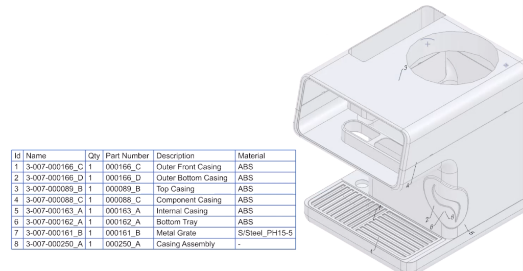
A part table is a useful way to show the different components in an assembly in a list and provide information about them, such as name, quantity, part number, description, and material. It also allows you to label the components in the 3D model with corresponding numbers that match the part table.
To create a part table using NX MBD rules, we will use the example of a coffee maker assembly. As we are responsible for the outer casing of the coffee machine, we open the sub assembly of the outer casing in another window before we add any of the available MBD rules.
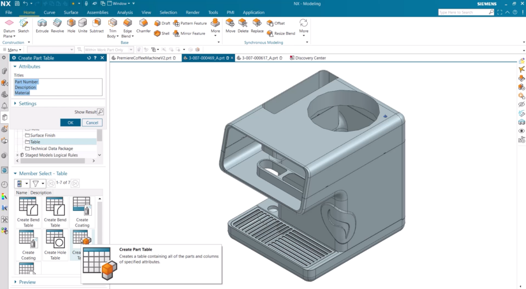
To add out-of-the-box MBD rules, we can access the reuse library on the resource bar, where we can find various MBD rules that are ready to use. These rules are organized into different categories and subfolders, and we can see a tooltip for each rule when we hover over it.
For our purpose, we will go to the MBD Logic Rules subfolder and select the Part Table rule. This rule will automatically generate a part table with predefined attributes and label the components in the 3D model. We can also modify the attributes and the layout of the part table according to our needs.
After applying the Part Table rule, we can see the part table with all the relevant information. We can also see that each component in the 3D model has a number that corresponds to the part table. To view each component more clearly, we can use the emphasis function, which will make the model translucent and highlight the selected component. This way, we can easily identify each part of the outer casing.
Creating Size Dimensions for Holes in a Part
Another common task that requires PMI is creating size dimensions for holes in a part. This is a common task that requires PMI, and it can be very tedious and time-consuming if done manually. However, with NX MBD rules, we can automate this task and create size dimensions for all holes in one step. We will use an example of a part with many simple holes with different sizes and tolerances. We want to assign PMI to all these holes to have a complete digital product definition in the 3D model. There are many MBD rules that we can choose from, depending on our needs.
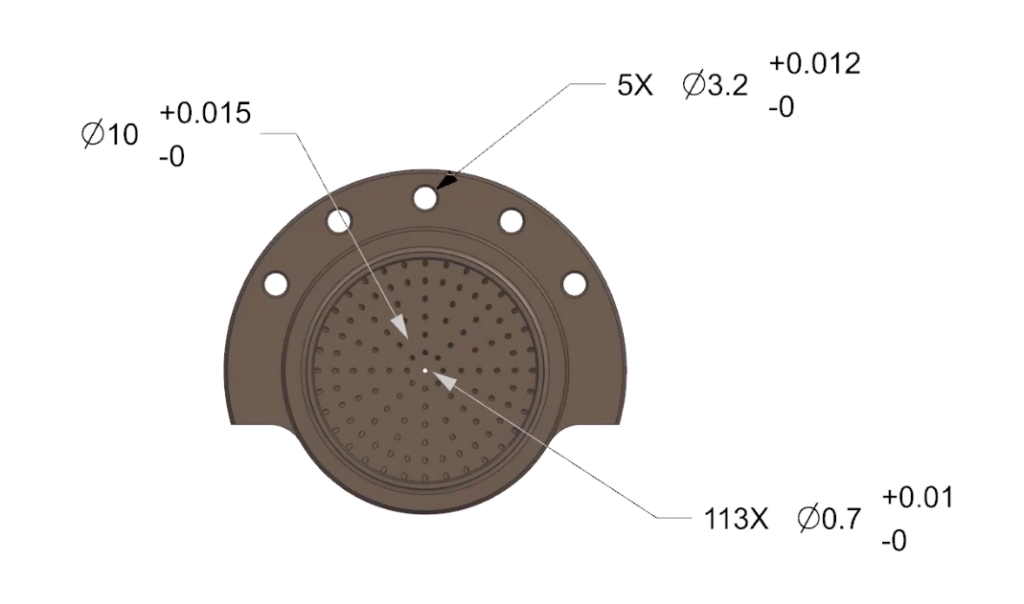
For our purpose, we will use the Create Size on Holes rule. This rule will create PMI that shows the count, diameter, and tolerances of the holes. We can see a tooltip for each rule when we hover over it, so we know what to expect. We can also change the tolerance for specific parts if we want. The rule uses hole size and tolerance tables when creating the PMI, so different sized holes have different tolerances. The PMI created by the rule is smartly selected and associated with the holes in the 3D model.
Using NX MBD rules has another advantage – they can keep track of changes in the 3D model and adjust the PMI accordingly. For instance, if we remove one of the holes because of a design change, the PMI that is linked to the hole will also change. The PMI on the 3.2mm holes will be retained, which indicates that the rule needs to be revised. We can use a built-in interface to check and approve the changes made by the rule.
Conclusion
We hope this blog post has shown you how easy and convenient it is to use NX MBD rules to create PMI for your 3D models. NX MBD rules can help you save time, reduce errors, and improve communication in your design process. You can use the over 100 out of the box MBD rules that are available or create your own custom rules that suit your specific business needs.
Continue your journey with NX
Watch the Draw Cage tips and tricks video here ▶️
Watch the Design Space Explorer deep dive here ▶️
Take me to the NX design blog 📚