Multi-Kinematic Animations | NX Tips and Tricks
Welcome back to our Tips & Tricks series! As we get ready to move into the new year, we still have a few more key functionalities we’d like to highlight from the June 2023 release of NX™ software. This week, we’ll be reviewing some tips for creating multi-kinematic animations with NX Animation Designer.
In the accompanying video below, we’ll be showcasing how to use inverse kinematics to automatically create a motion path for a drill press. And, just in case you need a refresher on NX Animation Designer, you can check out our ‘Getting Started with Animation’ post from a few weeks back right here.
Let’s jump right in!
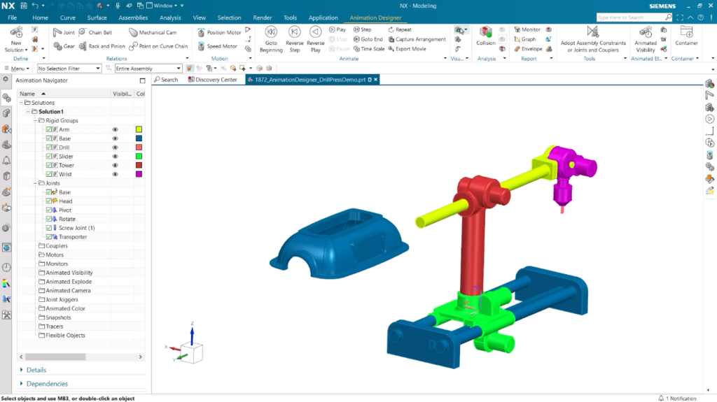
View and assign rigid groups and joints within an assembly
Inverse Kinematics will automatically create a motion path for Rigid Groups to go from a set point to a desired point—making it easy to create smooth and seamless animations. Using the Animation Navigator, you can easily view the different Rigid Groups as well as view which bodies are grouped together and which are separated, based on their assigned color. From here, you can also examine the Joints in the graphic display to determine how they are positioned in the assembly. Each of these Joints will then be used to constrain the motion of the drill press when we use the Inverse Kinematics tool.
Use Inverse Kinematics to create a motion path for two destination points
Once you’ve set your Rigid Groups and Joints, you can use the Inverse Kinematics command to create a motion path. In our video example, the rigid group is going to be the drill press spindle, and our destination will be the center point of the hole on the part we are drilling.
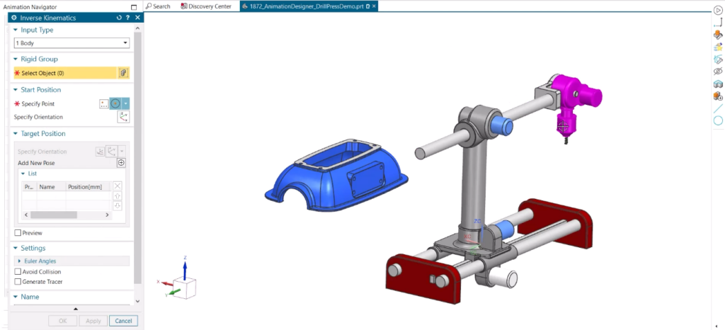
The coordinate systems of the starting and destination points will need to line up, and an easy way to achieve this orientation is to select an axis along with a desired face for reference. For the drill press spindle, our destination point will need to move back in order to accommodate the drill bit. This is also easily achieved by designating a second spindle destination point after the first destination point has been reached, simulating the drill bit piercing the part.
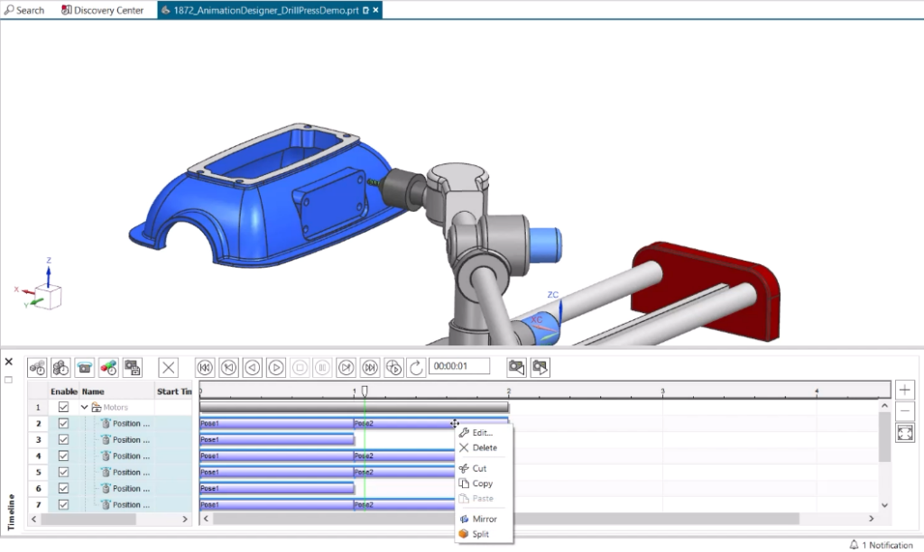
We can now view the generated motion path! The animation of the drill press provides us with a better understanding of how each Rigid Group moves within the assembly—and we can inspect this motion in more detail by opening the timeline to move through the animation.
Mirror motion to complete the animation sequence
Now that the motion path animation has been generated, one last step for us to take is to have the drill press fully return to its original position. To do this, we simply select all of the motion that has already been created in the timeline and then choose the ‘mirror’ option. Our final animation will now demonstrate the complete sequence of the drill press from beginning to end.
Conclusion
Thanks for stopping by to learn more Tips & Tricks from the June 2023 release of NX! We hope that you’ll continue to explore how Animation Designer and multi-kinematic animations can help bring your designs to life.
As always, please be sure to let us know if there are any NX topics you’d like us to cover in future Tips & Tricks posts.