NX Join | Part One | NX Tips and Tricks
Introduction
Another entry of our Tips and Tricks series is here, this time delving into NX™ Join. As with all of our Tips and Tricks blogs, we aim to provide you with easy to read, easy to follow and easy to learn snippets of information. We hope these are then useful takeaways for improving your productivity and experience with creating your designs in NX.
Identify joins quickly through identification markings
Any tool that can help with speeding up identifying parts of your design is a win! We understand that designers want to be able to easily access all parts of their design simply and easily. With NX Join, rather than users having to load in point joins, they have the option to display their join as a shape of symbol. This can help users to simplify complex assemblies, while still identifying how they plan to assemble their products. Alternatively, users still can display their assemblies with loaded fasteners or hardware. This can simply be done by selecting the “load hardware” option when creating joins.
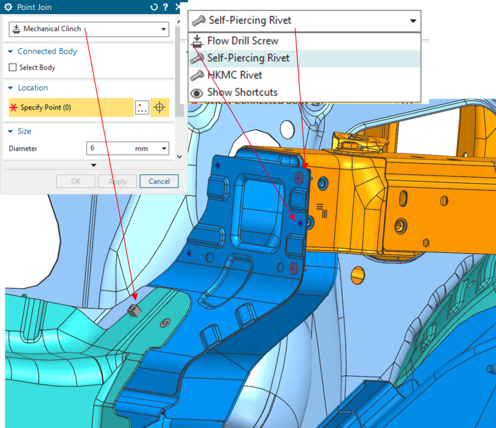
When creating a point join, users need to decide what hardware to use. For this case, we are going to select a protruding bolt with the smaller diameter option. Once this has been selected, next we can see a checkbox to decide if we want to load our hardware into the part. In this instance, we are unchecking this box so we can explore symbolic displays of our point joins like we’ve already mentioned.
In our example in the video below, we will change any of the tolerances or dimensions, but the last thing we will explore is the symbolic display section. From here, our users can decide what shape they would like to represent our point joins, as well as its own color and size.
To loop back around to the continuous point that we remind our users of with each release, saving valuable time. This tool specifically is very useful when you want to avoid loading and focus more on the production of your design.
Edit multiple joins at once through Edit Point Join
The next tool we are going to look at within NX Join is the Edit Point Join tool. The tool allows users to quickly change Point Joins that have already been created. With a drop-down box to select which type of Point Join they wish to edit; users can efficiently gather the joins that they wish to change. Once these joins have been selected, users are able to view a parameter table with all the values that they can change for their joins that they have chosen. Following these steps and utilizing this tool, makes it easy to compare and alter your joins to optimize your product’s design.
To bring your attention to our demo, and our example, you are able to quickly go in and alter one or more of your previously created point joins from the dropdown box. At the top of the dialogue box is a filter to determine what type of point join you want to alter. You can see when rivet is selected, the fasteners do not highlight. For this example, we are going to take two of these fasteners and edit their size and symbolic display shape. When opening the parameter table, there is a wide variety of alterable dimensions. This makes it easy to make small changes downstream when using joins. Remember to then select ‘Okay’, as your model will then update and reflect the changes.
Use Join Note PMI annotations to clean up display
The final tool we’re going to look at in this entry is the Join Note PMI (Product & Manufacturing Information) annotation. Users can easily create associated PMI for their Joins by utilizing the Join Note tool under the annotations tab. This makes transitioning large assemblies from the design phase to the production phase a much easier process. Users can quickly select attributes from their Joins, such as diameters and thickness, and quickly translate their respective values to PMI. With a wide range of settings and options, this tool is highly customizable to fit users’ needs.
In our example, we are prompted to select the join we would like to create PMI for, and underneath we are given a list of attributes to choose to add to our PMI.
You can see here, in our example, we have selected diameter hold type and fastener type, but please bear in mind that these selections will vary from user to user. After this, you can choose your orientation as well as if a leader line is attached to the information. Once everything looks good, select ‘apply’. You should then be able to see that this new data has already been loaded in and reflects the data values of this particular join.
Conclusion
And that draws our NX Join Part One to an end! Hopefully you can see the benefits this tool has in down the line manufacturing. We hope you have followed this ‘Tips and Tricks’ entry, as we have explored how to create point joins, the ability to represent them as symbols, how to go back and edit their values, and lastly, create PMI for manufacturing. Stay tuned for Part Two of this instalment – we will see you soon!
Continue your journey with NX
NX Join Part One | NX Tips and Tricks | YouTube Video


Comments
Leave a Reply
You must be logged in to post a comment.
I need help with the installation of NX student edition, I am getting an error “invalid attemp to load library”. I did the installation several times, with the same result.