Elevation Lines | NX Tips and Tricks
Since the latest release of Siemens’ NX™ software in our continuous release program that debuted in December, our team has been gathering all the best hidden workflow tips to share with you! Aiming to excite and motivate you as a user, our next topic in the Tips and Tricks Series will yet again be looking at a Building Information Modeling (BIM) element. In this installment, we will be discussing the impact of Elevation Lines in your design and how you and your team can benefit from these enhancements with NX. For the best experience, follow along with the video linked down below!
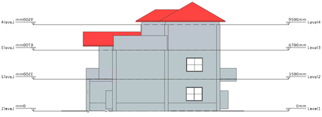
Elevation Lines Definition: A network composed of lines/datums used for positioning and defining of BIM Design components in the Elevation view of your BIM Design structure assembly.
Quickly position building elements with Elevation Lines
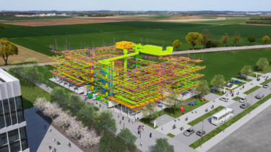
Without the use of BIM design, taking a 2D drawing of physical structures and converting them into a 3D representation would seem ambitious. By utilizing an array of BIM commands inside of NX, these conversions can happen in a few mere clicks.
From stand-alone structures to full assemblies, one of the most important parts of any design is getting your dimensions correct. Elevation lines take the guess work out of creating dimensions for each building component introduced into your sketch. What may seem like a very basic concept is crucial to a well-executed prototype. With the help of Elevation lines, you can now quickly create new building elements in a matter of clicks that fits your design and adheres to your design standards.
Easily position building components when referencing Elevation Lines
Elevation lines have more functionality beyond creating multilevel buildings. One tip to getting the most out of your elevation lines is to reference them when adding additional building components. For example, say you want to put in a staircase from the first to second floor. Here you can reference the elevation lines from the floors to perfectly place your staircase in your design. The same can be said about adding in doors, windows, and walls into your design.
Top Tip: Use the ‘Move component’ command to add point-to-point references from your building element to your Elevation lines to align them perfectly.
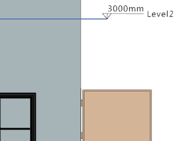
Modify Elevation line display properties to adhere to standards
Finally, what may seem like a simple approach to customizing your design — modify your elevation line display properties to accurately depict the visuals you need. From the width and color to the font and line length, you can display these properties in a way that fits your design standards. By utilizing this featured tip, you can complete consistent and repeatable designs.
Conclusion
We hope that you are enjoying this series of Tips and Tricks inside of NX. As mentioned above, the capabilities and customization of Elevation Lines are essential to adhere to your designated workflow. Applying these tips within your BIM designs should increase your design productivity and quickly allow you to design building elements at a grand scale!