PCB design best practice: ECAD/MCAD co-design
When we think about the PCB design best practices that fall into the digitally integrated and optimized pillar, we need to start off with electro-mechanical (ECAD/MCAD) co-design.
What is ECAD/MCAD co-design?
ECAD/MCAD co-design is the collaboration between ECAD and MCAD domains during product design. This collaboration enables both ECAD and MCAD to optimize their designs within tight form-factor constraints while still meeting quality, reliability, and performance requirements.
What’s not working?
I can tell you from three decades of experience struggling with the handoff between electrical and mechanical, that the legacy way we’ve done things can be error prone. Data can be incomplete or have errors when you’re handing it off in legacy formats such as:
- .DXF files
- Manual emails
- PDF drawing
- Handwritten drawing
What are the roadblocks?
One of the biggest roadblocks you may run into when going up against legacy methodology is organizational resistance to change. Sure, it’s an indirect roadblock, but it is a big one. Another roadblock might be siloed teams and siloed tools that just don’t integrate well. You also have unfamiliar formats in the data that you’re handing off.
Best practices: ECAD/MCAD co-design
When we talk about best practices, the format that’s the latest and greatest right now is the IDX format for the ECAD/MCAD collaboration. We should look for a methodology that enables context based, integral collaboration between the domains and the disciplines. The value you’re going to get from that is that you have streamlined, integrated collaboration that minimizes the risk of errors during the data exchange.
How it works: ECAD/MCAD co-design
In an optimized flow the MCAD designer might start collaboration after adding data pertinent to the electronic designer to a design, such as the board outline and critical component placement like connectors.
This information then needs to be passed to the electronic designer so that it can be considered during the development of the PCB. As a part of the process certain items can be set to be owned by the mechanical designer which means that these items can only be edited by the mechanical tool. Doing this helps eliminate accidental changes to items critical to the mechanical aspect of the design, that would cause unnecessary rework downstream.
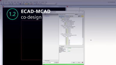
Starting collaboration with electronic designer is as easy as creating a baseline. With the baseline created, the electronic designer can look at the baseline and preview the information in the baseline file. Items like the board outline, mounting holes, placement obstructs, and components all show up in the tree view, and allow the designer to make sure that nothing in the file would interfere with any work that may have already been done. Once the baseline is applied to the project, an assembly file can also be imported, which contains the mechanical models and NX assembly.
Further changes in either domain can be sent by creating proposals, with the other domain expert having the ability to accept or reject the proposed changes.
Visit our website or watch this video to learn more about ECAD/MCAD Co-design.