E/E architecture evolution, part 1, some history
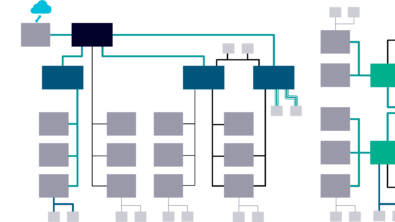
I recently covered the basics of an E/E architecture diagram, so now lets explore the architectures they describe and how they have evolved up to most of the new vehicles you can buy today. I will cover the current trends soon.
Single networks
The first data networks commonly connected powertrain systems, initially the engine and gearbox, and these to the instrument cluster, also enabling diagnostics via fault codes with emissions systems, and expanded from these as time went on. This simplified improvements in emissions, efficiency, drivability and performance, allowed for diagnostics to be reported to a service bay tool, and more detailed warnings to the driver of detected faults. Various network technologies were used initially, such as VAN in PSA vehicles, standardized in ISO, or SAE J1850 used by Ford, GM, and Chrysler, albeit in slightly different forms by each OEM.
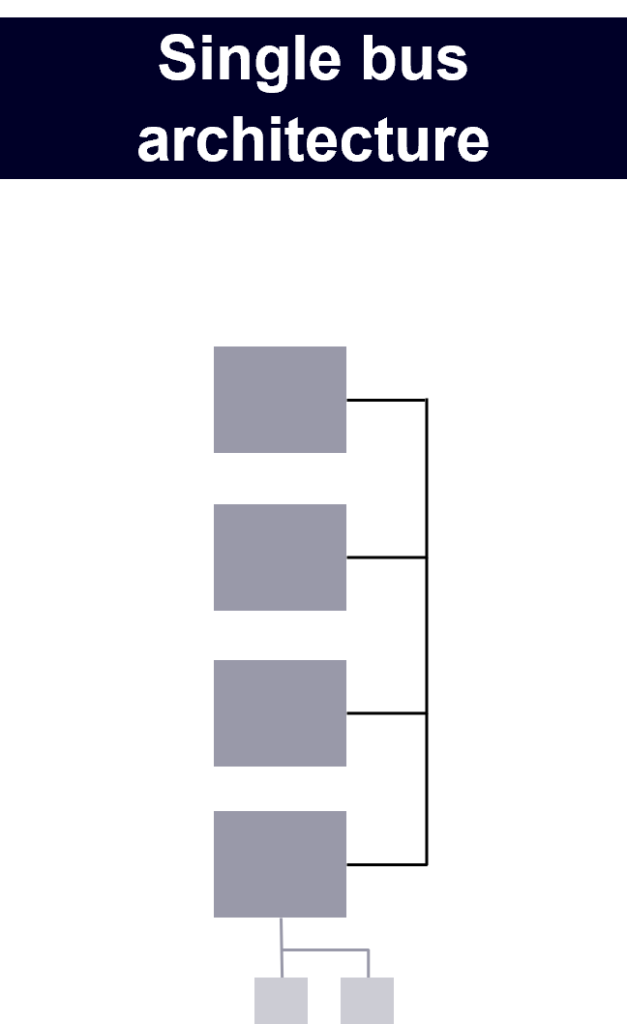
However Bosch introduced CAN bus, standardized as ISO 11898, in the 1980’s which has become an industry standard still in used today with various updates, and newer versions such as CAN FD, and CAN XL being developed. CAN differed from earlier networks in truly allowing Tier 1 suppliers to use the same base components and hardware for multiple OEM customers, helping drive the economies of scale, of the CAN components, and whole ECU’s, even if OEM’s still have their own implementation rules based on the standard, refined for robustness with the way each OEM designs it’s E/E architecture. Adopting a common standard aligned well with many OEM’s wanting to outsource some, then most or all of the increasing number of ECU’s in vehicles to Tier 1 suppliers who could benefit from economies of scale if at least the same hardware could be sold to several OEM’s.
Twin CAN bus networks and a gateway
CAN bus is commonly used at a few common data rates, 125kbit/s, 250kbit/s, 500kbit/s being most common, but up to 1Mbit/s is supported by the standard. Lower data rates could be implemented with cheaper physical layers, avoiding twisted pair wires for example, and over longer distances, commonly needed when there were few networks connecting ECU’s around the vehicle. The first vehicles to start to use multiple CAN networks, that were connected typically included a ‘slower’ (really lower data rate/baud rate network, the electrons travel at the same speed), and a ‘faster’ higher data rate network. This split allowing real time control related signals to be sent and received more frequently between closely located powertrain components, whilst enabling body related functions to be spread around the vehicle.
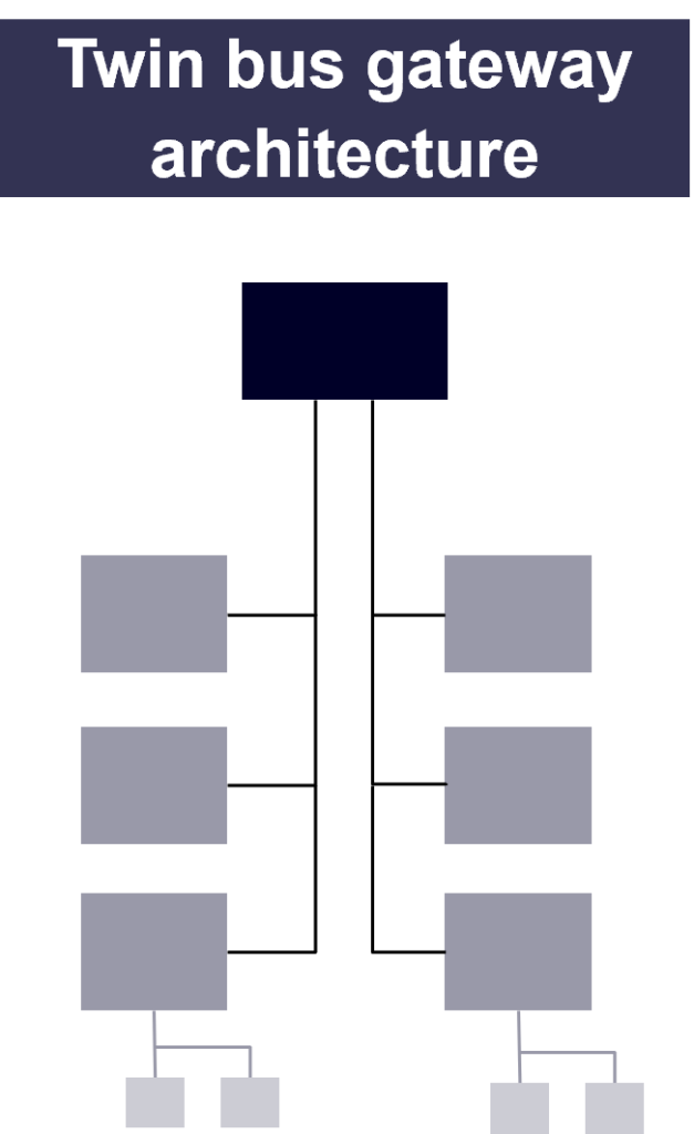
Connecting these networks, to enable functions to use data from elsewhere in the vehicle is done via gateways, at various times these have been dedicated modules, sometimes hosting functions, or within a module which consumes data from both networks, such as a Body Controller or Instrument cluster. Commonly with CAN gateways, and similarly with LIN bus (Local Interconnect Network) gatewaying with a common 8 Byte payload, the gateway can forward the whole frame, or repack the needed signals into a new frame specific to the second network, broadly speaking more gateway processor load results from signal gatewaying, more network bandwidth is consumed by frame gatewaying, so a mix is often, but not always used.
More networks with a central gateway
Over time, more features are added to vehicles adding to the ECU count, traditionally a new feature, even if built using some existing functions would need a new feature ECU to host the additional embedded software. Adding features, powered by the underlying functions of the vehicle means sharing more data, network signals, each network has a limited capacity for the amount of data it can transmit, not to mention that the physical layer can only reliably connect a given number of ECU’s on any given network, albeit design rules and tricks and tips to extend this do vary. Different OEM’s have different rules for both, depending how they setup the physical layer, termination circuits, wiring standards and more, and how they design the communication with more periodic or event driven traffic.
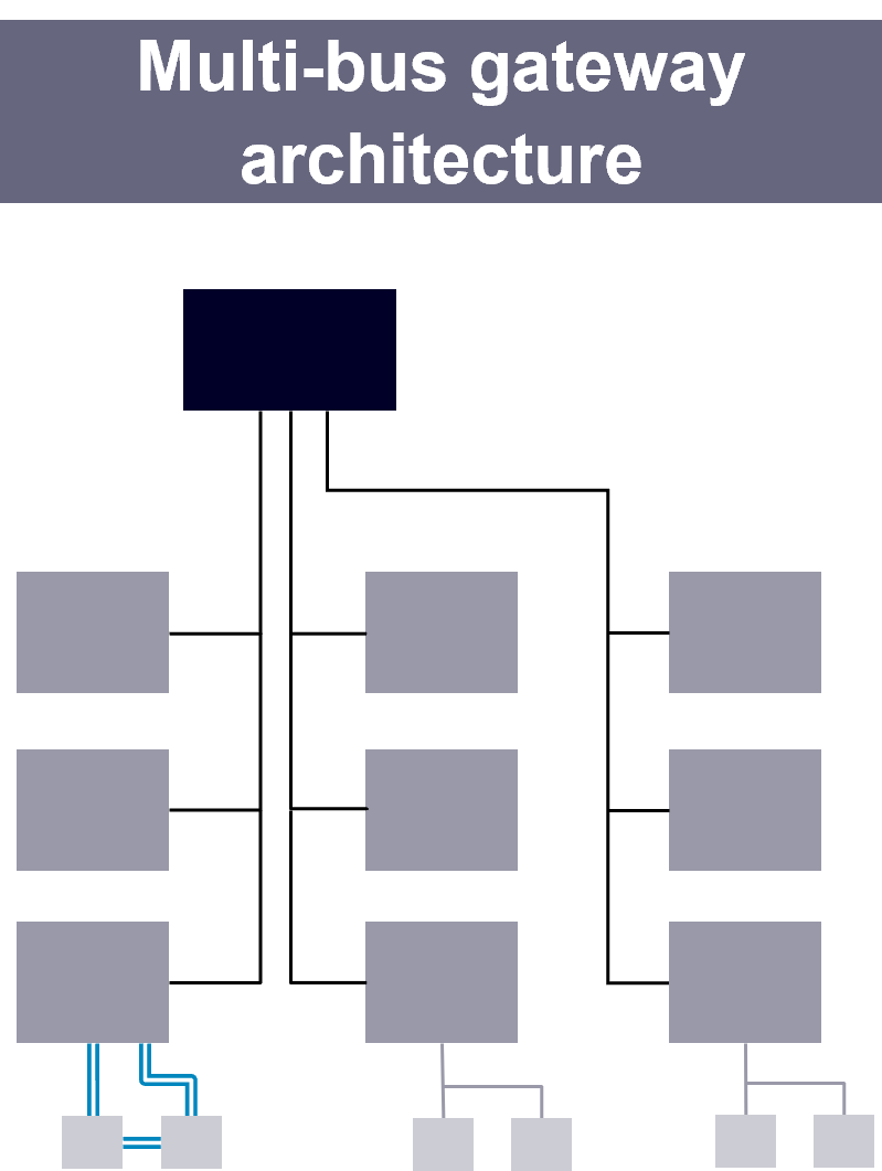
Some time ago I discussed some technology and techniques used by Volcano technology to reliably increase the bandwidth utilization on CAN bus, even then there is a limit, and spreading the ECU’s over more networks becomes necessary. It’s common for OEM’s to outsource many, sometimes all, of their ECU’s to Tier 1 suppliers, potentially 2 or more different suppliers across an OEM’s full range of vehicles for each ECU type. Simple CAN drivers, and OSEK operating systems enable communication on CAN bus, but to reliably communicate between many ECU’s, ensuring consistent interpretation of the data, more complex data structures, data protection mechanisms for functional safety and cyber security, requires additional specifications.
Whilst Volcano wasn’t the only commercial option, many in the Automotive industry wanted a software standard available from multiple vendors, or directly from the Tier 1 suppliers, increasing competition, but with interoperability. AUTOSAR was the solution, several OEM’s, Tier 1’s and Tier 2 vendors collected together combining knowledge and technology, now 20 years ago, to develop a standard for the industry as the AUTOSAR consortium. Using AUTOSAR across the E/E architecture has allowed OEMs to reliably configure ECU’s to communicate across the larger networks now common on vehicles without constraining themselves to a small selection of Tier 1 vendors.
Today the design capabilities of Volcano that were in Vehicle Network Architect, then Vehicle Systems Architect Com, with many more recent additions are available in Siemens CapitalTM Network Designer software, and Siemens has an up to date AUTOSAR offering in the Capital Embedded product family.
Functional consolidation, backbones and functional domain controllers
Over the last few years it has rapidly become common for premium and luxury vehicles to have a very high number of ECU’s, over 100, sometimes over 150, and thus networks, usually these have become networks dedicated towards specific functions, so what might have been a Powertrain and Chassis network is now likely at least 2 networks. This leads to a complex E/E architecture resulting in a strong desire where practical to consolidate functions into fewer ECU’s, and while AUTOSAR helps with the portability of applications through it’s use of abstraction layers and Virtual Function Bus (VFB) abstractions, there is still a commercial complexity in re-use and re-integration of functions, especially where the software code was written by a supplier, not the OEM.
This led to the development of specific Functional Domain Controller ECU’s, that are the target to host much of the cross functional, complex, management type software functions, where practical simplifying many of the other ECU’s to sensors, actuators, and hosts of lower level functions, albeit some real time control can be best located in these ECU’s for more deterministic functions.
Increasing data exchange, over more complex networks has lead to the introduction of higher data rate networks such as FlexRay, which was designed for automotive use cases, and Automotive Ethernet, which is an adapted form of Ethernet, with a robust, low cost physical layer, but using standard software as a base, with the addition of various protocols and tools, such as TSN (Time Sensitive Networking), SOME/IP and DDS to meet automotive use cases, with interoperability ensured through AUTOSAR adoptions of the standards.
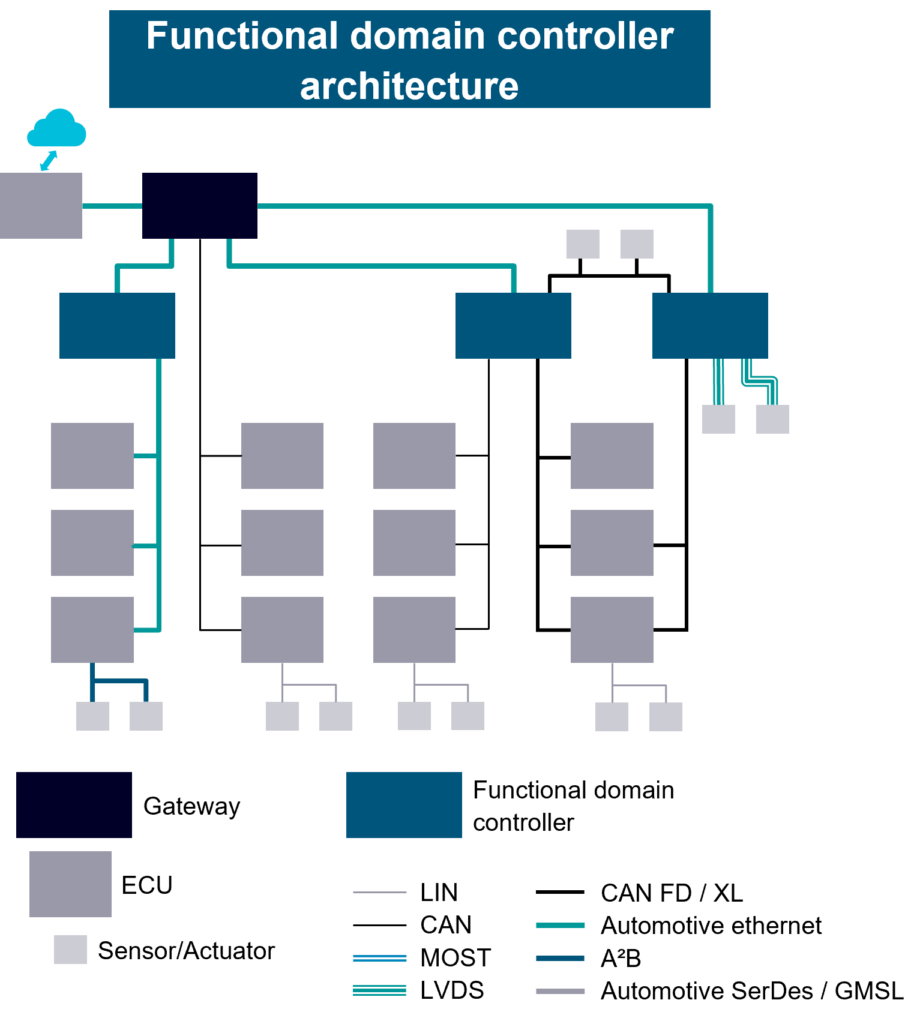
It should be noted that my example E/E architecture diagrams are somewhat simplified, with considerably less than 100 ECU’s, to illustrate the differing character of these architectures without becoming overly complex.
Summary
E/E architectures have evolved over time, adapting as complexity increases, moving from a single network, then CAN bus, with a few ECU’s, through several CAN buses with a central gateway. Then as the number of ECU’s increased through the 10’s towards 100 in luxury vehicles, to functional domain controller architecture with a backbone network. I’ve introduced some topics here that I will return to in more detail, but also included links to learn more now on topics which cannot wait.
More on this topic to come soon, next I’ll cover current trends in E/E architecture… but if you want to learn more now, the following reading and watching are a good place to start.
- On-demand webinar: Advanced in-vehicle network design for electric and autonomous driving
- On-demand webinar: Overcome the challenges in electric vehicle embedded software development
- White paper: Modern automotive cybersecurity through secure communication, strong authentication and flexible firewalls

