Five Steps to Double Patterning Debug Sucess
By David Abercrombie, Mentor Graphics
Shhhh…David Abercrombie’s revealing the secrets of successful DP debugging!
Has debugging double patterning (DP) errors got you pulling your hair out, or wishing you had pursued that career in real estate, like your mom suggested? Now you can unlock the secrets of DP debugging in five easy steps! Once you learn these steps, you’ll be the envy of your team, as you deliver clean DP designs on schedule, and still have time to eat lunch each day!
So, what are the five steps of successful DP debugging? Are you alone? Okay, lean in and listen closely…There are five types of errors you typically find in a DP design layer (excluding any errors associated with using stitches), and the order in which you debug them can make the difference between success and an endless insanity loop of debug-fix-check. I hope you’re taking notes, because here are the five steps in which you should debug your DP errors…
1. Debug all minimum opposite mask spacing errors first.
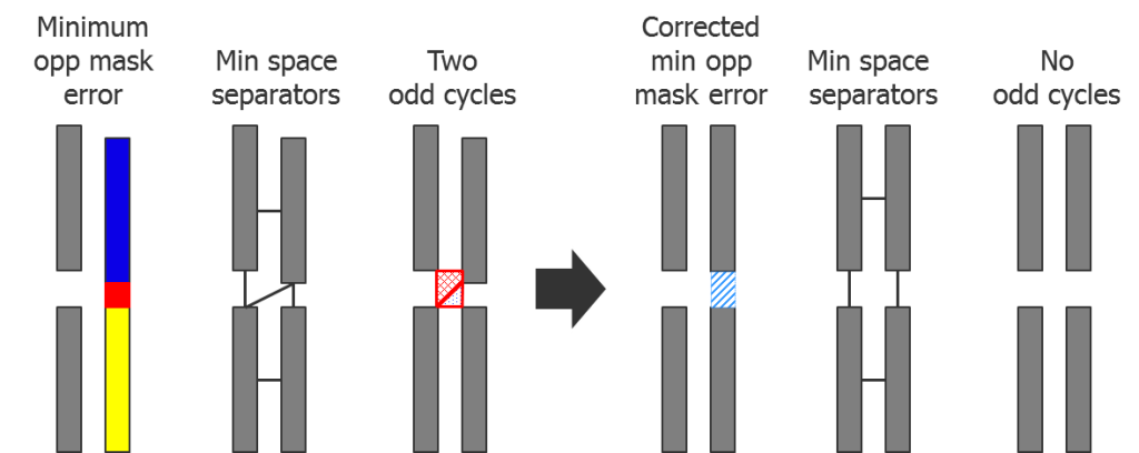
This condition is the most fundamental DP error you will encounter. Minimum opposite mask spacing errors, just like traditional design rule checking (DRC) spacing errors, involve only two polygons and the space between them. However, there is no coloring solution that resolves the error. In addition, violating a minimum spacing constraint can create other misleading DP errors, as shown in Figure 1.
Figure 1: Minimum opposite mask spacing errors can generate unnecessary odd cycle DP errors.
When these two polygons violate the minimum opposite mask spacing constraint, they also create a diagonal tip to tip separator constraint in the layout, which leads to two odd cycle violations between the original two polygons and the two adjacent polygons. Because designers often assume the best way to fix an odd cycle is to adjust any of the spaces involved in the odd cycle, they can end up making two corrections to fix these odd cycle errors, without even correcting the original minimum spacing violation. However, if you fix the minimum spacing violation first, the odd cycles don’t even occur, so you fix both issues at once.
2. Correct all self-conflict same mask spacing errors.
These errors consist of single polygons that have notch spaces between themselves that violate minimum same-mask spacing constraints. This error type is also isolated to a single polygon, but when this polygon interacts with other polygons, other error types can occur. Fixing this error eliminates these secondary errors (Figure 2).
Figure 2: Self-conflict same mask spacing error causing unnecessary odd cycle DP errors.
The red polygon is in conflict with itself. This error is usually flagged by highlighting the polygon. The separator constraints that form in this layout example create an odd cycle error of one. Again, fixing the self-conflict error fixes the odd cycle error as well.
3. Next, resolve all anchor self-conflict errors.
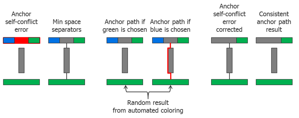
Anchor self-conflict errors are the result of conflicting anchor requests associated with a single polygon. Depending on the automated coloring solution your DP tool selects, an anchor path error may or may not be created. Resolving these errors removes that uncertainty (Figure 3).
Figure 3: Anchor self-conflict errors can potentially cause anchor path errors.
The layout contains a single polygon with two color anchor markers. The separator interactions with other polygons create a path from this polygon down to the bottom polygon. Due to the marker conflict, the DP tool has no guidance, so it randomly decides which color to assign to the polygon. If the tool selects the green anchor, no anchor path error is created, but if the tool chooses the blue anchor, an anchor path error to the green anchored polygon at the bottom is created. However, if you eliminate all anchor self-conflict errors first, any anchor path errors you encounter will be deterministic, rather than random and unpredictable.
4. Fix all odd cycle errors.
Because odd cycle errors can lead to an anchor path error (Figure 4), fix all odd cycle errors next.
Figure 4: Odd cycle errors can lead to anchor path errors.
Due to the separator interactions with other polygons, the odd cycle interacts with two anchored polygons at the top and bottom, creating an anchor path error. By adjusting any one of the spacings in the odd cycle, both the odd cycle error and the anchor path error are fixed.
5. Finally, fix the anchor path errors.
Why save these for last? If you try to fix the anchor path error in Figure 4 before looking at the odd cycle error, you might decide to adjust the space between the top anchor and the middle polygon, or the space between the bottom anchor and the middle polygon. Both of those corrections fix the anchor path error, but leave the odd cycle error in place. Correcting all of your odd cycle errors first can save you a lot of debugging time by making some of those anchor path errors simply vanish.
Following these five steps won’t magically make all your double patterning errors disappear. But they will help you avoid making unnecessary design changes, as well as reduce your overall debugging cycle time. Double patterning design is challenging enough; don’t allow error complexity to make it any harder. Try following these five debugging steps on your next layout, and I think you’ll be pleasantly surprised.
For more information about double patterning debugging, watch “Why IC Designers Need New Double Patterning Debug Capabilities at 20nm” with Jean-Marie Brunet of Mentor Graphics.
Author
David Abercrombie is the Program Manager for Advanced Physical Verification Methodology at Mentor Graphics.
Liked this article? Then try this –
Video: Why IC Designers Need New Double Patterning Debug Capabilities at 20nm
This article was originally published on www.semimd.com

