How to Survive the Perfect Storm of Changing Fill Requirements
By Jeff Wilson, Mentor Graphics
Using hierarchy in the fill process provides greater control for the designers, improves consistency throughout the design, and reduces fill runtime and file size.

Even if you think you’re prepared for anything, the perfect storm can erupt unexpectedly, creating havoc and chaos. In integrated circuit (IC) design, we’re currently seeing the makings of such a storm when it comes to the growing complexity of fill. The driving factors contributing to the growth of this storm are the shrinking feature sizes and spacing requirements between fill shapes, new manufacturing processes that use fill to meet uniformity requirements, and larger design sizes that require more fill.
Before 90 nm, fill was used primarily to improve planarity during the chemical mechanical processing (CMP) stage of manufacturing. Designers added only as much fill as needed to achieve the desired density targets. Because the file size was manageable, the runtime for adding fill did not add excessive time to the schedule, so designers typically waited until near the end of the design flow to run fill at the top level of the design.
In a typical 20/16/14 nm design, fill can now easily exceed a billion shapes. At leading-edge processes, fill is used to mitigate the effects of rapid thermal annealing (RTA) and stress effects, and to improve the results of electrochemical deposition (ECD), etch, and lithography. These new uses of fill means fill strategy has shifted from minimizing the amount of fill in a design to maximizing the amount of fill added, which obviously impacts both fill runtimes and database size.
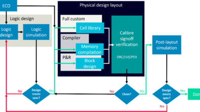
Two new fill techniques aimed at reducing the impact of these changes are the ECO fill flow and the hierarchical fill flow. I’ve discussed the ECO fill approach previously, so now let’s explore the hierarchical fill method.
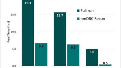
Using hierarchy in the fill process can provide greater control for the designers and improve consistency throughout the design. Equally important, hierarchical fill can also reduce both fill runtime and file size, in a couple of ways.
The first technique is to use hierarchy within the fill shapes themselves. The key to this method is to adopt a cell-based approach to fill (Figure 1), which benefits both flat and hierarchical runs because the fill output now contains cells, rather than billions of individual fill shapes.
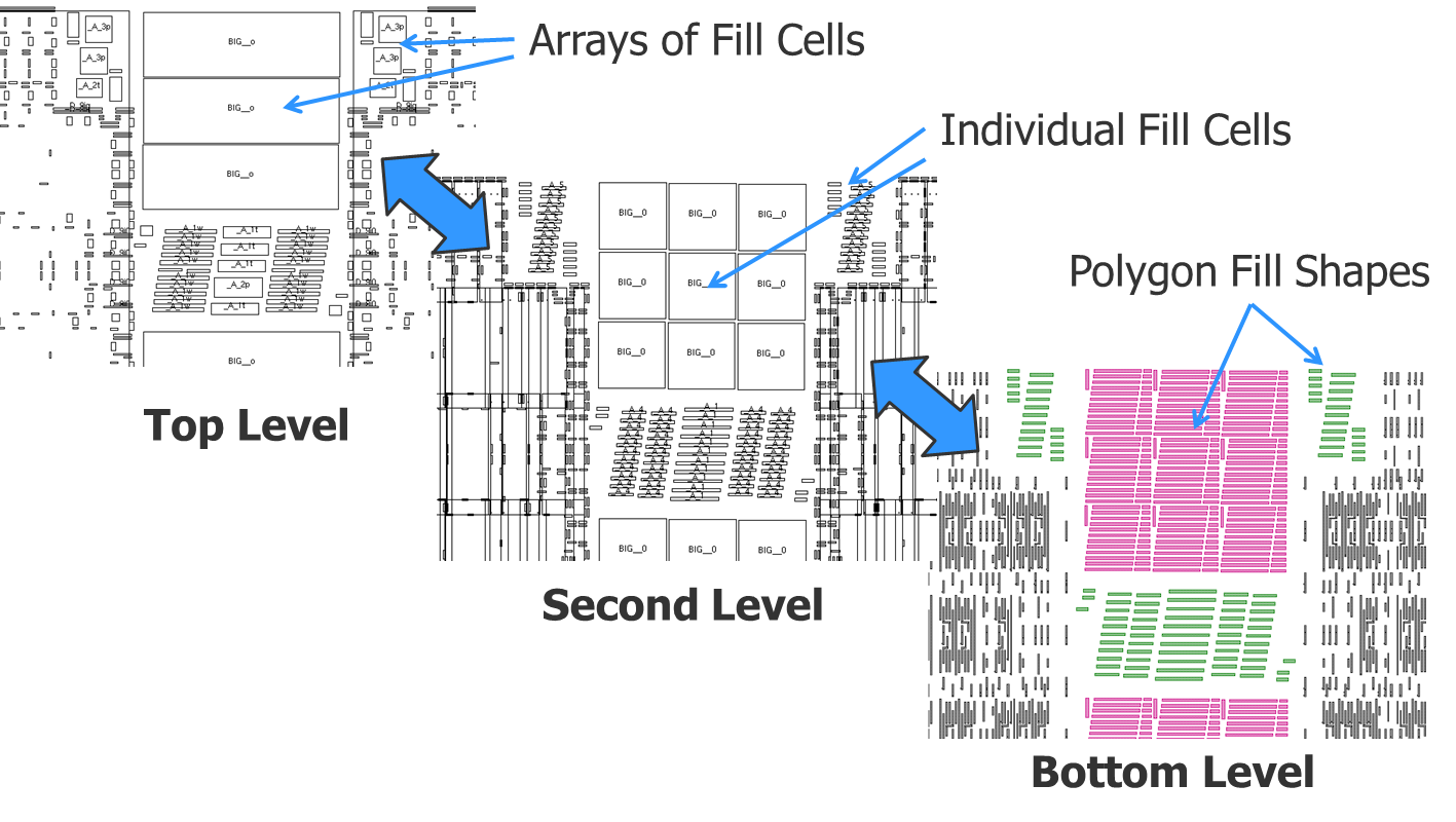
Figure 1. Cell-based fill allows designers to define a fill pattern (fill cell), using correct by construction techniques. These cells can be placed within the designated regions, reducing both runtime and file size.
The second method of using hierarchy to reduce the impact of increasing fill is to make use of the design hierarchy. If you have multiple instances of a block, it is logical that filling it once reduces both the time required to add the fill shapes and the file size. The cell-based fill approach not only simplifies coding for deck developers and reduces file size, but by placing cells with a correct-by-construction fill solution that considers all the spacing rules across all layers, insertion rate increases while concurrently reducing runtime and file size.
In addition to reductions in runtime and file size, there are a number of design consistency issues that benefit from using a hierarchical fill approach. For example, the requirement for a uniform fill around interconnect layers reduces the available spacing and increases the electrical impact of the fill. A hierarchical approach keeps the capacitance from the fill shapes consistent across different instantiations of the same block, ensuring that the electrical impact and timing of these blocks are the same throughout the design. This hierarchical fill consistency is also valuable in reducing the post-fill runtimes of both design rule checking (DRC) and layout vs. schematic (LVS) comparisons because the checks only have to take place once. Post-tapeout tools and processes can also take advantage of this improved consistency, such as manufacturing operations performed in the foundry, like multi-patterning decomposition, mask data preparation, and optical process correction (OPC).
Obviously, then, there are a number of positive aspects that this type of flow delivers, but of course, it is not without challenges and trade-offs. This approach does require additional effort over the traditional “push the button at the end” fill technique, because the designer must decide the appropriate level at which to add fill. As with any hierarchical approach, operating at too high or too low of a level in the
design hierarchy significantly reduces the benefit. Too high, and the results start to resemble flat fill. Too low, and designers may reduce the benefit of hierarchical fill by making the interactions between blocks too complex.
All of these constraints complicate the placement of hierarchical fill cells, but as technology continues to shrink, and runtime and file size continue to grow, the question is not if your design flow will need to support a hierarchical fill flow, but when. Design methodologies for hierarchical fill range from a user-driven flow with a hands-on approach to a completely automated flow using new EDA tool capabilities. Companies must determine the proper fill methodology for their design style, but regardless of the methodology they choose, there are a number of questions that must be answered. Designers must determine the optimum level of hierarchy at which to add fill, and define the correct halo size required to meet the gradient density rules. If companies want to implement an automated fill solution, they must determine if they have a complete solution available that includes both the EDA tools with the required capabilities, and a rule deck that supports the hierarchical fill flow and methodology.
Given how easy running a flat fill at the end of the design process is to use, it is logical that companies will want to use that approach as long as possible. However, I strongly recommend that your design team look ahead, and begin learning and planning for the transition to hierarchical fill. Familiarizing yourself with the methodology, acquiring the necessary technology to support your design flow, and analyzing your designs in progress are essential to a successful and timely implementation. Approaching the end of a design cycle with time-to-market pressures mounting is not a good time to find out that your flat fill is going to take over 24 hours to run and add billions of shapes into your design, significantly increasing the post-fill runtimes for both DRC and LVS and delaying your product’s introduction to market. That’s a storm that can destroy everything you’ve worked for.
Author
Jeff Wilson is a DFM Product Marketing Manager in the Calibre organization at Mentor Graphics in Wilsonville, OR. He has responsibility for the development of products that analyze and modify the layout to improve the robustness and quality of the design. Jeff previously worked at Motorola and SCS. He holds a BS in Design Engineering from Brigham Young University and an MBA from the University of Oregon. Jeff may be reached at jeff_wilson@mentor.com.
This article was originally published on www.semimd.com