Rigid-Flex Material Considerations

Flex and rigid-flex designs refer to a PCB that is partially or entirely constructed using flexible rather than exclusively rigid substrates. The use of flex results in reduced impedance discontinuities, while producing more rugged and reliable PCBs. Creating a flexible PCB does have several draw backs, requiring unique Rigid-flex DFM practices, as the increased complexity of manufacturing results in an increase in manufacturing costs, and additionally, the specialty materials themselves are considerably more expensive.
Rigid-flex designs also have improved electromechanical functionality, including dynamic bending, vibration and shock tolerance, heat resistance, and weight reduction. These characteristics make them popular in medical, automotive, military, and aerospace applications that require dependable field operation. The ability to bend portions of the circuitry also makes them a preferred choice for flat panel displays, cellular devices, and wearable technology.
Use of flexible materials allows for greater adaptability of their designs, allowing designers to take advantage of the available 3-D space and create an overall denser design.
As opposed to a rigid PCB, flex PCBs do no contain fiberglass between their copper layers. Instead, they come attached to a flex core consisting of a glass-less material, typically a polyamid film. The consistent nature of a flex PCB means that there are fewer connection points needed to join two rigid boards together, and therefore fewer points of failure. The lack of glass also comes with the advantage of providing a much more uniform impedance value across the board, and likewise reduces non-deterministic loss sources caused by micro-environmental effects like glass-weave skew.
Flex circuitry are typically infused with Polyimide, as it offers a durable, relatively cheap, heat resistant option. However, depending upon application, the substrates and films could also consist of polyester, a PVF, PFA, TPU, Poly Carbonate, or PTFE. Each of these options present unique application opportunities, from providing transparent solutions, to high temperature operation, or versatile flexing for smart-clothing.
Unique attributes of rigid-flex materials
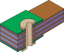
The materials used in rigid-flex are a bit different than those used in rigid designs. It is important to understand with Type 4 rigid-flex designs that the same flex core carrying the copper in the flexible portion of the board is also present within the rigid substack. Whereas with the flex portion the core and copper planes were covered by a coverlay, now within the rigid substack that coverlay is overlapped slightly and then replaced by either a low-flow, or no-flow prepreg material. These are used instead of traditional pre-preg materials to keep the resin from flowing into the flexible substack, as this would cause it to become brittle when hardened. Low-flow prepreg materials.
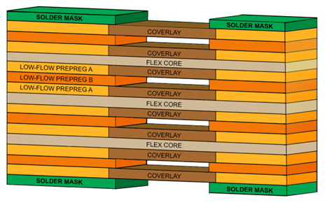
In the rigid-flex illustration shown above, the coverlay’s over the flex core overlaps the flex region, typically penetrating 50 mils into the rigid section of the board. A resin (Low-flow prepreg A) is added to support the flex core within the rigid portion of the board. These layers are then connected and laminated together using a second resin system (Low-flow prepreg B) which contains the exact footprint of the rigid section and is used to secure the coverlays together within the board.
No-flow and low-flow pre-pregs form the basis for a rigid board and so, unlike the flex cores, contain fiberglass weaves within them to reinforce the board.
Types of flex and rigid-flex PCBs
IPC-6013 specifies four different types of flex and rigid-flex PCBs:
Type 1:
Single-sided printed boards containing one conductive layer, with or without stiffeners.
Type 2:
Double-sided flexible printed boards containing two conductive layers with PTHs, with or without stiffeners
Type 3:
Multilayer flexible printed boards containing three or more conductive layers with PTHs, with or without stiffeners
Type 4:
Multilayer rigid and flexible material combinations containing three or more conductive layers with PTHs
Adhesives
There are many ways to adhere copper to flex dielectrics in rigid-flex designs and choosing the right one depends on the application where it will be used. Where copper is bonded directly to the base material, adhesive can be added. Sometimes stiffeners are needed to reinforce a flex area for components or routing holes. Depending on the flexibility specs of the application, copper can either be electrodeposited (ED) which is less flexible but has a lower cost or rolled annealed, which is more flexible but has a higher cost.
Coverlays and bondpiles
Coverlays are flexible materials, typically on the outside of a flex substack, that protect and insulate the flex circuitry on surfaces and prevent it from lifting. A typical coverlay construction has a polymide dielectric on top and an adhesive on the side facing the copper. Bondpiles are similar to coverlays, but they are used on inner stripline layers, with adhesive on both sides and the polymide dielectric in the middle. They are used to glue two flex cores together.
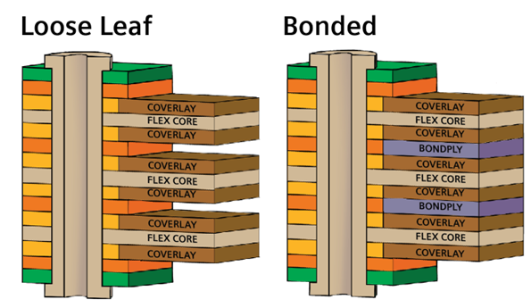
Flex cores
Flex cores typically span all substacks, carrying the copper from one end to the other. Flex cores without adhesive are used for high-performance rigid-flex applications. Adhesive-based flex cores are less expensive and generally used for single- or double-sided or low-layer-count flex applications.
Hatched planes
Flex reference planes are often etched with a hatched pattern to reduce the amount of copper used and make them more flexible. The traces must go over the knuckles in the crosshatching. In differential pairs, the pair pitch and diagonal pitch should be equal to minimize impedance and traces should be right over the knuckles.
Tools for building a rigid-flex stackup
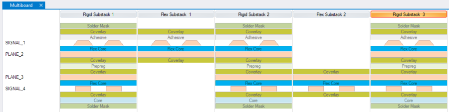
Flex and rigid-flex PCBs are a unique technology, and there are many unique considerations in their design, some of which we detailed here. In order to select the right materials and techniques for each application, designers need visibility into the various material options available to them. Therefore, an extensive materials library, like that offered by Z-planner, is critical when creating the stackup design for flex or rigid-flex PCB. It features multiple laminate options, including many flex materials from over a dozen laminate manufacturers, so designers can choose the one that meets their needs at the lowest cost.
Where to learn more about rigid-flex stackups
This article barely scratches the surface of what today’s PCB designer should know about rigid-flex stackups. Bill Hargin has developed extensive expertise in this field, which he shares in greater depth, in his recently published ebook, Stackups – The Design Within the Design, available now from I-Connect007.
Explore Valor NPI with our Online Trial
Explore Valor NPI with our free online trial and find out how easy it is to implement the world’s most advanced DFM software. With no download or installation necessary, this simple guided tour provides immediate hands-on experience. Select your desired workflow: