Top 5 rigid-flex design guidelines

Rigid-flex DFM
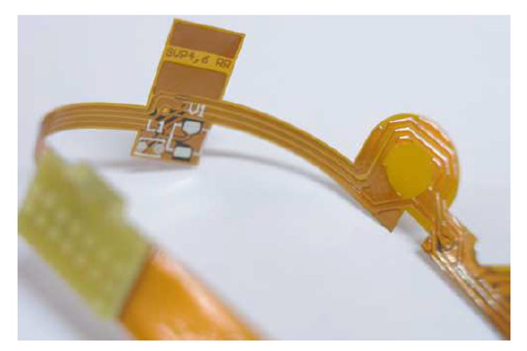
I am not sure if you have seen a rigid-flex circuit before, but I bet you must have used a product with rigid-flex circuit inside, because rigid-flex is a very common technology now, and it has even become an indispensable part of our daily life. Mobile phones, electrical watches and even eyeglasses are all now using this technology.
The growth of rigid-flex products is driven by the proliferation of smaller form, low weight and high reliability factors of products, so you can imagine there will be more and more products using rigid-flex technology.
For an end user, except for the fact the product is smaller and more convenient to use, there is not much difference in the user experience when a product is using the rigid-flex design compared to a conventional rigid printed circuit board (PCB)
However, for an electronic design or manufacturing engineer who developed and manufactured the rigid-flex product, it is much more complex for them to design and manufacture a rigid-flex product. The flex circuit’s thinness makes them more delicate, and they are more susceptible to accidental damage during manufacturing.
Guidelines are always very helpful to guide the engineers to design and manufacture a product in lower cost, high efficiency and good reliability – the same as is true for rigid-flex designs.
Flex circuits and the interface between rigid and flex segments can have problems that do not exist with standard rigid PCBs. The following are top 5 rigid-flex design guidelines to facilitate you to design and manufacture a robust rigid-flex circuit board:
1. Rigid-flex transition
Just like the broken headphones, the most vulnerable location is always the transition between flexible cable and rigid insertion end. The transition between rigid and flex circuit board is also the area for careful design. The rule-of-thumb for conductor spacing is 5 mm between the rigid board and the bend area of the flex circuit. Conductors closer than this are much more susceptible to breakage. Also, without proper spacing, the coverlay under the rigid area can peel and expose copper.
2. Minimum bend radius requirement
One successful practice to design a flex design is considering the bend requirements. Both the material type and thickness will impact the bend capability of the flex session. The minimum bend radius is usually calculated by using the flex thickness multiply a factor. Bend to fit applications use a factor from 6 to 20 depending on the layer count. Dynamic bend application is typically using 100 multiply the thickness of a 1-2 layers flex design.
3. Conductor width
Conductor width is also especially important. A safe rule-of-thumb for conductor widths is to design them at least five times as wide as they are thick. Our recommended practice is to use the thinnest copper trace that will safely carry the intended signal and then adjust trace width accordingly. For example, if a signal can perform as required on ½ oz. copper, the trace width should no less than 3mil.
4. Air gap in rigid-flex
For multiple layer flex design, it is better to configure the flex layers in independent pairs, instead of designing all flex layers together. This configuration is known as “air gap” or “loose leaf design”, with an air gap designed between each of the flex layer pairs. Another benefit of the construction with air gap is that it can significantly increase the flexibility of the design.
5. Thermal expansion
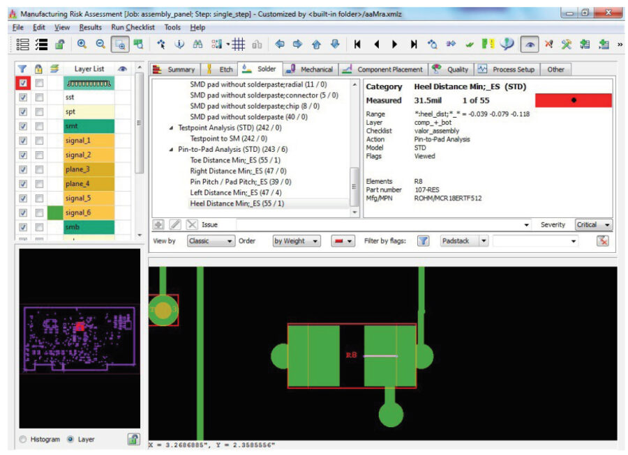
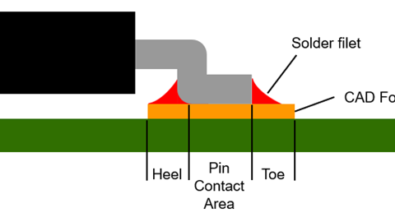
Most adhesive-based flex base materials are unfilled, which may result in unchecked thermal z-axis expansion, which makes vias and other features prone to delamination and causes potential intermittent responses after components have been soldered to the surface of the flex material. To combat this, include a more robust pad stack compared to the rigid areas for components soldered on the flex material. Rigid-flex circuit designs are increasingly popular with the miniaturization of technology and the explosion of wearable devices. Rigid-flex circuits require unique manufacturing processes and thus have unique manufacturing process constraints. To ensure and optimize rigid-flex circuits for manufacturing, a dedicated Design for Manufacturing (DFM) solution is the best tool to improve the yield, cost and reliability for rigid-flex circuit designs. Valor NPI is such a solution that brings the manufacturing knowledge into the application to provide the expertise to run DFM on rigid and rigid-flex designs.
Valor NPI can identify issues associated with the top 5 rigid-flex design guidelines presented here and many others.
Explore Valor NPI with our Online Trial
Explore Valor NPI with our free online trial and find out how easy it is to implement the world’s most advanced DFM software. With no download or installation necessary, this simple guided tour provides immediate hands-on experience. Select your desired workflow: