Memory BIST for automotive designs
By Steve Pateras, Mentor Graphics
Memory BIST is evolving to meet the demands of automotive ICs.

Built-in self-test (BIST) is the standard approach to testing embedded memories. Over the years, memory BIST has evolved to meet the demands of new markets and technologies. Its latest capabilities respond to the requirements of ICs for the fast-growing automotive electronics market.
BIST reduces manufacturing test times by enabling much greater memory access, and allows test patterns to be applied at full memory speeds. BIST solutions today usually include advanced debug and diagnosis support, built-in self-repair for yield improvement, and algorithm programmability for adapting to new defect mechanisms in more advanced technology nodes.
But, the demands facing silicon test never stand still, and a whole new set of requirements is currently driving further evolution in memory BIST.
Automotive electronics is one of the larger semiconductor growth segments right now. ICs for this market must adhere to more stringent requirements for quality and reliability than those going into consumer electronics. These requirements are largely driven by safety standards such as ISO 26262 and certain Automotive Safety Integrity Level (ASIL) targets.
ISO 26262 compliance requires the adoption of more advanced test solutions. In particular, for an IC to achieve necessary levels of reliability, memory BIST capabilities must be enhanced to support a number of in-field test requirements.
Power-on self-test
Whenever a car is turned on, all the electronics are checked to ensure their proper and safe operation. This routine check on power-up is enabled by the inclusion of a power-on self-test (POST) capability within all devices.
A programmable POST architecture is shown in Figure 1.
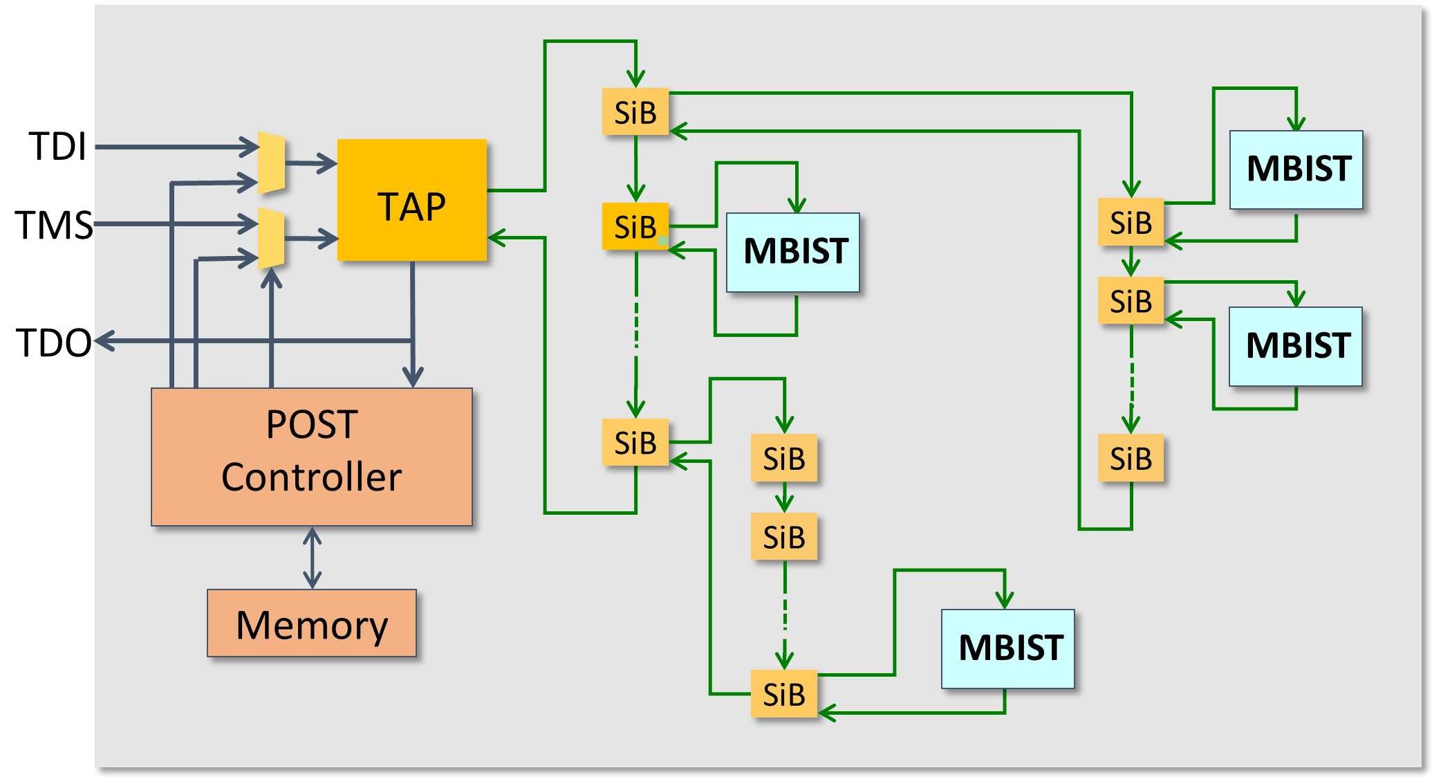
Figure 1: Programmable POST architecture for Memory BIST (Mentor Graphics)
An IEEE 1687 (IJTAG) based network is used to provide access to all of the BIST controllers distributed throughout the design. This hierarchical network of scan insertion bit (SIB) switches allows for versatile and efficient communication to the controllers. An IEEE 1149.1 test access port (TAP) provides external access to the IJTAG network and is primarily used within the manufacturing test environment.
A POST controller is also included in the design. It can take over the TAP signals and drive the necessary commands to any and all of the BIST controllers. Any desired sequence of tests can be executed by programming the necessary commands into a memory accessed by the POST controller. This memory can be dedicated or shared with other system functions.
The POST architecture also supports on-line memory BIST testing – periodic testing during functional operation. This is becoming an increasingly common requirement for automotive parts.
Destructive and non-destructive memory BIST tests
The key difference between running memory BIST tests at power-on versus on-line is that some form of memory access arbitration is required between the functional logic and the BIST controller during on-line testing. A handshaking protocol can be implemented within the memory interface logic to handle this. The handshaking protocol and BIST controller together can then implement either destructive or non-destructive testing.
Destructive memory BIST test
Destructive testing is what is generally used during manufacturing test. In this case, the handshaking logic disables the memory from functional use so that the memory BIST controller can carry out its full test uninterrupted. Although this is the simplest approach, destructive testing has the significant drawback of affecting system performance, as the memory-under-test is not available for a significant period of time. There is also the added overhead of saving the memory pre-test content to another location and restoring the memory once the testing is complete.
Non-destructive memory BIST test
For these reasons, non-destructive testing appears to be more popular. In this approach, the memory BIST controller tests the memory using a series of short sequences of transactions, often referred to as bursts. A burst will typically only last for a small number of clock cycles (c.20-30) and target different memory locations each time. The entire memory is therefore tested over a large number of short memory BIST sessions.
The approach is non-destructive because the memory locations that are modified by a burst are saved and restored during each burst by the MBIST controller. Functional performance is not significantly affected because the bursts are only initiated when the arbitration logic determines the memory is free.
Faster memory repair
Another in-field efficiency improvement driven by automotive requirements relates to memory repair.
When memories are repaired during the manufacturing test process, the fuse information necessary to carry out the repairs is typically stored in an on-chip eFuse array. This information must be transferred to the memories at power-on.
In the past, this transfer was performed through one or more serial scan chains to reduce routing. In automotive applications, however, power-up times have strict limits and this serial transfer process often takes too long. Faster transfers are required. One technique here involves distributing the eFuse array into smaller local eFuse arrays within each design core and then directly broadcasting the local eFuse array output to all of the memories within the core.
The automotive electronics market continues to grow and rapidly evolve. Even the more mature test solutions like memory BIST must continue to adapt to meet the needs of this challenging market segment.

Liked this article? Then try this –
White Paper: Automotive Semiconductor Test
Datasheet: Hierarchical ATPG Compression Tessent TestKompress
This article was originally published on www.techdesignforums.com
Comments
Leave a Reply
You must be logged in to post a comment.
the post idea is great and new to me, but that is not I want to say, but I want to say is that putting all whole chip mbist sib into one single daisy chain isn’t good to me, hierarchy design is future,I am trying to look for a solution like tap+wtap(star topology)+ijtag,can’t find a reference flow in mentor website?
The SIB hierarchy shown in the figure is only to demonstrate that this is possible. You can use a unique SIB per MBIST controller at the top level to provide similar direct access as you would have with a star topology.