Tips and Tricks from Forum Users #28

An assortment of short tips and tricks based on the discussions in the Solid Edge forum.
Compiled by @TusharSuradkar
Due credit is given to respective contributors.
A quick list of the previous compilations:
T&T #01, T&T #02, T&T #03, T&T #04, T&T #05
T&T #06, T&T #07, T&T #08, T&T #09, T&T #10
T&T #11, T&T #12, T&T #13, T&T #14, T&T #15
T&T #16, T&T #17, T&T #18, T&T #19, T&T #20
T&T #21, T&T #22, T&T #23, T&T #24, T&T #25
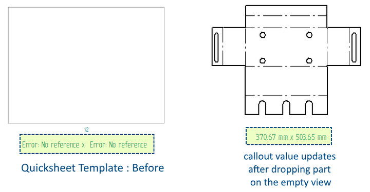
1. Is there a way to have a callout on a template that calls out the flat pattern cut size that would change depending on what file you choose?
Tip: Sure.
Create a callout with text
%{Flat_Pattern_Model_CutSizeY/CP|R1} x %{Flat_Pattern_Model_CutSizeX/CP|R1}
Where the two variables are exposed from the sheetmetal model file and put this callout besides a Quicksheet template.
Contributor: @TusharSuradkar
2. Every time I print a DFT file I get black circles on top of my drawing. How can I fix this?
The circles seem to appear on the location of my lines/rectangles.
Tip: You perhaps have wrong line style thickness and the option to scale line thickness during printing turned off.
Open that draft, go in Options – View and check “Show as printed”
In this way, you should be able to identify the geometry with the wrong line thickness and fix it.
Contributor: @Fiorini
3. How do I do a helical feature with the profile perpendicular to the helical path?
I can create a helical feature both parallel and perpendicular to the axis, but this makes the cross-section narrower than the original profile relative to normal to the helical path.
I am trying to model the channel produced by a helical cut by a CNC end-mill which always maintains the same dimensions when viewed perpendicular to the helical path. How do I orient the profile to be perpendicular to the helical path, rather than parallel or perpendicular to the helical axis?
Tip: I believe you will need to generate a helical curve (Surfacing ribbon) and then use a Solid Sweep (cutout) to get what you want.
Contributor: @KennyG
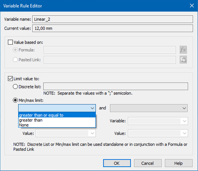
4. Suppose you have a variable x, that you want to constrain to a certain range of values, say from x_min = 10 mm to x_max = 20 mm. So you enter the range (x_min=10.00 mm; x_max=20.00 mm) and all seems fine. However, you cannot actually set x to 10.00 mm or 20.00 mm because x has to be greater than x_min and less than x_max. This is a pain because if you want to set x at either limit you have to add or subtract some small value like 0.001 mm to or from the limit as appropriate. I think that that is a kludge/crutch and does not sit right with me. Can somebody please tell me why you cannot set a variable to be EQUAL to the defined limits in the Range?
Tip: In the Variable Rule Editor there is also a “Greater-Equal” and a “Less-Equal” condition available.
Just use that one!
Contributor: @wolha
5. How does one revert to an earlier MP?
I know this has been talked about long ago but it was hard enough to find old posts in the old functional forum. Now with this not-so-shiny new one, I personally deem it impossible.
You can revert to an earlier installed MP by uninstalling the current MP using the Installed Updates screen found under Control Panel, Programs, and Features, View installed updates
Tip: You will see the latest installed MP in the list. Select it and then select Uninstall at the top. It will then uninstall and revert back to the previously installed MP.
Contributor: @KennyG
Compiled by @TusharSuradkar


Comments
Leave a Reply
You must be logged in to post a comment.
All of the links to previous tips and tricks now redirect to the siemens community front page.
Thanks for pointing @nominus38
Tricks 1 to 14 were published by Matt Lombard of which 1 to 9 are linking fine, but 10 to 14 appear broken.
These are many other are problems with the new forum.
~Tushar