Solid Edge Tips and Tricks from Forum Users #32

Tips and Tricks from Forum Users #32
An assortment of short tips and tricks based on the discussions in the Solid Edge forum.
Due credit is given to respective contributors.
A quick list of the previous compilations:
T&T #01, T&T #02, T&T #03, T&T #04, T&T #05
T&T #06, T&T #07, T&T #08, T&T #09, T&T #10
T&T #11, T&T #12, T&T #13, T&T #14, T&T #15
T&T #16, T&T #17, T&T #18, T&T #19, T&T #20
T&T #21, T&T #22, T&T #23, T&T #24, T&T #25
T&T #26, T&T #27, T&T #28, T&T #29, T&T #30
1. Where are the “saved settings” shown in the dialog? How are they created and managed?
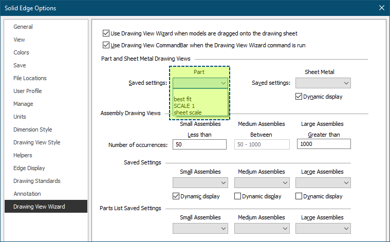
Tip: They are created in the Drawing View Wizard (“Saved Settings” button on command bar). It appears they are stored in a “DraftWizard.txt” file located in your “Reports” folder specified in the File Location settings.
Contributor: @KennyG
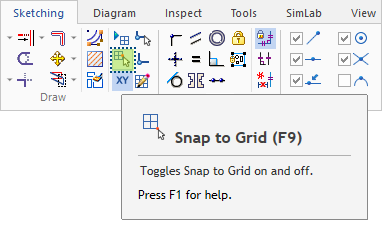
2. How can I activate the input fields X and Y in the Move command bar?

Tip: Turn OFF Snap to Grid.
Contributor: @bshand
3. I am getting this error after importing a step assembly and trying to delete items.
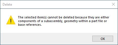
Tip: Are you trying to delete a sub-occurrence from a top-level assembly?
I’d suggest to first open the parent sub-assembly of the part you want to delete and then delete the part from there.
Contributor: @TusharSuradkar
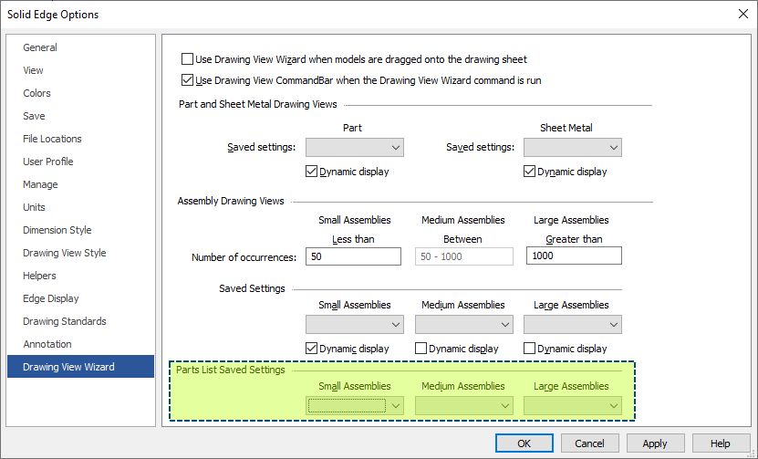
4. Someone has broken our template for assemblies, and I need to fix it, making it set to use a BOM setting already created. How in the world do I do this? I opened the template, put an assembly and correct BOM format on the sheet, saved it, then deleted the assembly and the BOM, and saved again. It still reverts back to a bad BOM format. I know I must be missing something simple, but at this point, I can’t find it.
Tip: Go to Solid Edge Options – Drawing View Wizard – Parts List Saved Settings.
Contributor: @Milro
5. I have an assembly and I would like to create a feature on a part in that assembly. I don’t want to create an assembly feature! How do I edit that part and grab edges and circles from other assembly parts to create the features? I don’t want those features to be dependent on the other assembly components at all. SO when I open that edited part is has a feature that is NOT dependent on the edges, circles, etc. that were pulled from the other components.
Thanks for any guidance
Tip: Presumably you have “PEERS” enabled……it is located on the Tools tab, while in sketch mode.
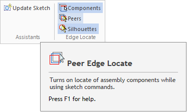
Contributor: @SeanCresswell
Tips Compiled by Tushar Suradkar


Comments
Leave a Reply
You must be logged in to post a comment.
ping testi