Demystifying Electromagnetics, Part 7 – Solenoids
A coil of wire carrying a current that produces a magnetic field is often referred to as a solenoid. However from an industrial perspective, the term solenoid refers to an electromagnetic device that causes linear motion of a ferromagnetic core or plunger. Strictly this is considered a linear actuator solenoid. Like a relay that relies on the movement of a hinged armature, a solenoid can be used to switch electrical circuits. It can also be used to pierce fruit, or at least attempt to.
A Somewhat Amateur Experiment
Before attempting to explain the electromagnetic behaviour of a solenoid using simulation, let’s take a look at a homemade one.
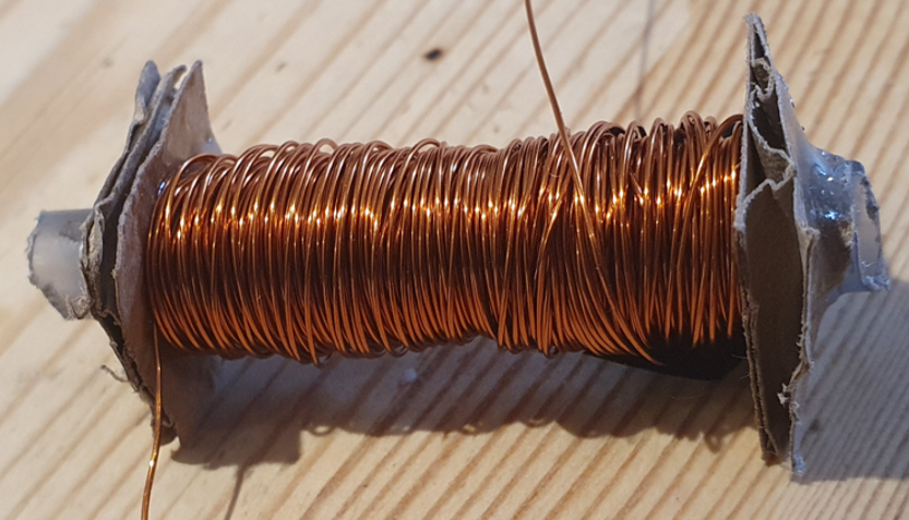
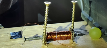
As is evident from its construction, I’m not very good at making things. The principle though is a coil of Copper wire wound around a cylinder, in this case a section of Biro (ball point pen) casing. The wire is enamelled so as not to short circuit itself. The wire coil is held in place by 2 glued on cardboard ‘washers’ (it was all I had to hand!).
A ferromagnetic core is placed half way into the biro. The only ferromagnetic core I could find was a nail. When a voltage is applied across the ends of the wire a current flows causing a magnetic field to be created which is especially strong inside the Biro casing. This causes the nail to itself become magnetised. Due to the nature of the resulting magnetic field (which we’ll look into in more detail next), the nail is forced into the biro casing coming to rest in the middle of it.
With apologies to anyone with even the vaguest talents at experimentation, here’s a video of the solenoid being ‘turned on’ and the nail moving as a result. The applied voltage was from a standard car battery (12.6V).
The nail and coil are actually attracted to each other. The 2 screws are there just to ensure the coil doesn’t move, so only the nail does.
Opposite Poles Attract (again)
As we saw in Part 6, the relay functioned by ensuring the ferromagnetic geometry was constructed so that the North and South poles were very close to each other. Opposite poles attract, and that is what caused the hinged armature to move.
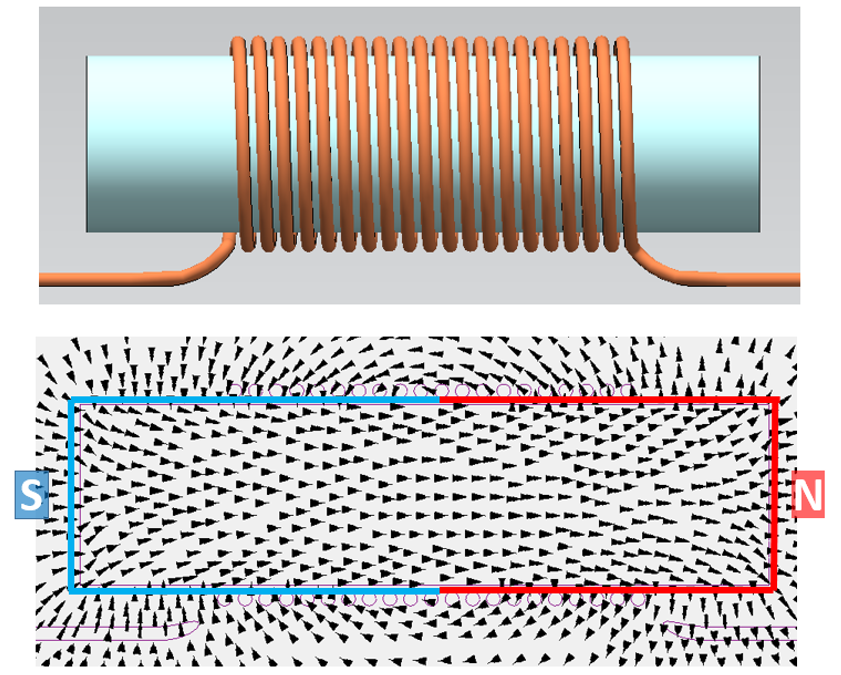
Let’s attempt to use the same simple concept of attracting poles to describe the movement of the ferromagnetic core. Using the previous Simcenter MAGNET coil model, here is the magnetic field when the core is partly inside the coil:
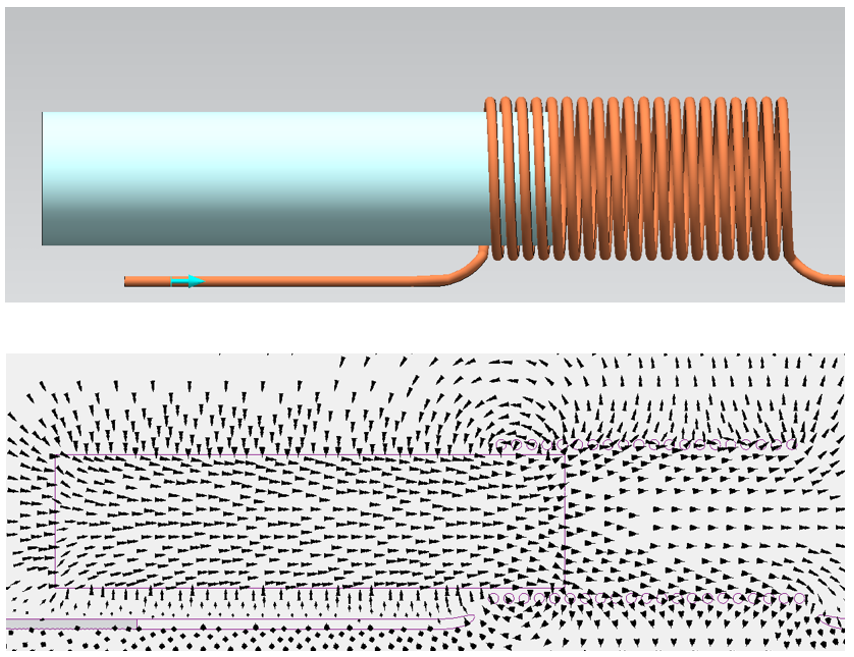
The core+coil together form a looping continuous magnetic field. The core+coil can be considered a single ‘object’. Its North and South poles are the surfaces where the magnetic flux respectively leaves and enters this ‘object’:
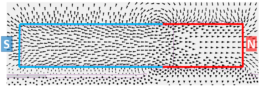
Opposite poles attract so this magnet is compressed. In fact all permanent magnets are in a state of compression, it’s just that they’re so mechanically strong, they don’t deform. Actually, even the coil alone is in a state of compression as Peter and Petronella demonstrated back in Part 3. For this core+coil object though, the air within the coil (the North pole bit) is easily displaced. With the coil fixed in space, i.e. the North pole fixed, it is the core that then moves to the right.
A compression equilibrium is reached when the core is centrally located within the coil:
Overly Simplistic?
There are various ways that the forces experienced by solid objects in a magnetic field can be explained. The above approach follows on from the ‘opposite poles attract’ approach in the previous blog. Just that this time, as the poles attract, the system can deform, specifically the core can translate. A purposefully simplistic explanation.
A rubber band analogy is another approach used to qualitatively describe magnetic forces:
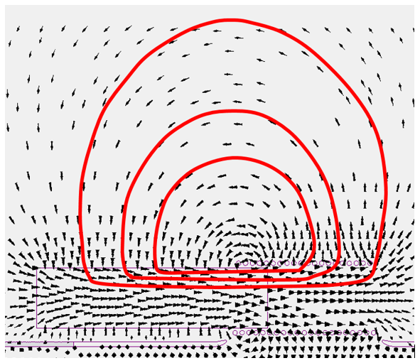
If you consider a ‘streamline’ (to use a fluid analogy) of the vector B field to be a rubber band, the system will seek an equilibrium where the elastic strain energy in all rubber bands is minimised. Even this approach is maybe overly simplistic in that the elasticity of the rubber band is itself a function of the strength of the B field along it.
Wobbling
As the core initially accelerates towards the centre of the coil, its momentum increases. If there are no friction or fluid forces acting on it, it will overshoot the central position and be attracted back the other way towards the centre. With no other losses in the system modelled, the core will continue to wobble around that centre point indefinitely. The following animation shows the core oscillating for the first few periods, approaching a repeating oscillation state:
In the solenoid nail experiment the friction between the nail and the biro casing dominated and the nail settled centrally in the coil with only one very brief overshoot. A friction coefficient could have been set in Simcenter MAGNET to model this loss.
Violence Against Fruit
“I have no special talents. I am only passionately curious.” – Albert Einstein, March 11, 1952. Inspired by the great man himself, I was curious if the nail solenoid was powerful enough to pierce, say, a grape (it was a slow day):
Answer: No.
I think it just annoyed the grape. The nail was too heavy / there was too much friction between the nail and biro casing / there wasn’t enough current being drawn / the grape wasn’t located close enough to the exit of the solenoid.
The force applied to the nail is a function of the magnetic flux density (B) within the solenoid. That flux density is in turn related to the number of coil turns x the current (this is Ampere’s law). Interestingly, for a fixed voltage supply, if you for example halve the number of coil turns, the electrical resistance will be halved and so the current drawn would double. So in fact whether you have 10 or a 1000 turns, the resulting magnitude of the magnetic flux density and so force on the nail will be roughly the same. Though of course if you have too few turns much more current would be drawn, Joule heating will start to dominate, temperatures will go up and things might melt.
Anecjoke
This blog series has been very DC focused to date. If you apply an AC to the solenoid, the core will still be attracted to the centre of the coil. Even though the current flips between flowing in one direction then the other, it doesn’t matter which direction the current is flowing through the coil, the core will always be attracted to the centre of the coil. The elasticity of the rubber bands, using the above analogy, are not direction dependent.
However with an AC supply, the current will be zero twice every period. The force on the core (a function of B which is a function of the current) will be zero at those time points. As the core in a solenoid device is attached to a return spring, the return spring force will move the core a little at those times. This creates a vibration. Vibrations are bad, they can spread, certainly be heard as a hum and over time loosen say a screw holding an enclosure in place. Which is what happened to a small enclosure supplying power to our bathroom extractor fan:
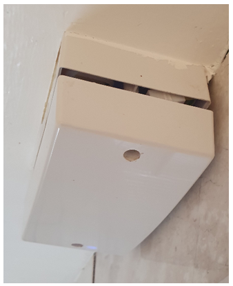
A good solenoid actuator will have a shading ring or shading coil. Some additional wire turns that help retain some of the magnetic flux density when the AC supply goes through the zero current point. A unit containing well designed solenoids costs more. You get what you pays for 🙂


