Demystifying Electromagnetics, Part 6 – Relays
Over the last 5 blogs in this series we’ve introduced a set of EM building blocks, fundamental behaviours that hopefully have been demystified by the use of analogy. At last, and not before time, we can get on to an actual application – Relays.
Electromagnetic Switches
The good thing about an electromagnet is that, unlike a permanent magnet, it can be turned on and off at will. All that’s required is to supply a current to the coil, which will create its own magnetic field and hence trigger a stronger magnetic field in a ferromagnetic core. Stop the current and the magnetic field disappears.
So what can you actually do with that magnetic field? How can the energy in the magnetic field be utilised? Although there many aspects of electromagnetics that benefit from demystification, the one thing we (should) all know is that opposite poles of magnets attract (be they permanent or electromagnetic). That attraction can cause a movement. That movement can be used to open or close an electrical circuit.
Getting the Poles Close to Each Other
As we saw in Part 5, a ferromagnetic core acts so as to increase the magnetic flux that is induced from the current in the coil. In addition, the extent of the magnetic field can be controlled and further ‘concentrated’ by modifying the shape of the core. In effect one can move the location of the North and South poles of the electromagnet. Let’s use Simcenter MAGNET to model the magnetic field for a range of differing core shapes, starting with a few simple ones:
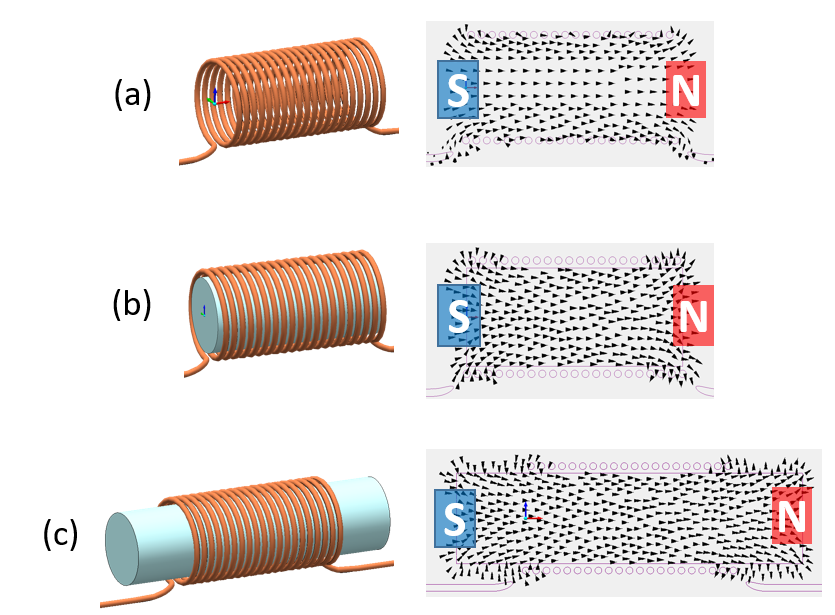
Simcenter MAGNET modelling the magnetic field. Vectors are of magnetic flux (fixed size). Vectors are not shown in regions of low magnetic flux density.
Without a core (a) a magnetic field is still created, it’s just less focused, more diffused. Even though there’s no core, there is still a notional South and North pole. Add a core just within the coil (b) and pretty much the same field exists, just more concentrated.
Increase the length of the core beyond the extents of the coil and the extent of the magnetic field also increases, pushing the poles further apart (c).
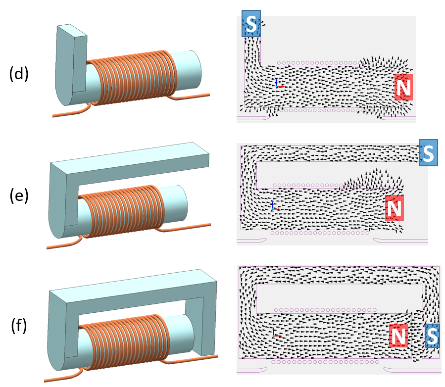
Add a vertical section (d) and then a horizontal section (e) and the location of the South pole can be further shifted.
By extending the geometry downwards (f), the 2 poles can be bought very close to each other. Now there is what looks to be a magnetic ‘circuit’. The magnetic flux passes through the air gap between both poles. Though due to the very low permeability of the air (compared to that of the core) it attenuates quite quickly over the gap. So, small gaps are better to maximise the amount of magnetic flux going round the circuit. Analogous to how thinner low conductivity interface materials in a thermal conduction system result in an increased heat flow for a given temperature difference.
Opposite Poles Attract
Not only can Simcenter MAGNET model the magnetic field, it also predicts the resultant surface forces:
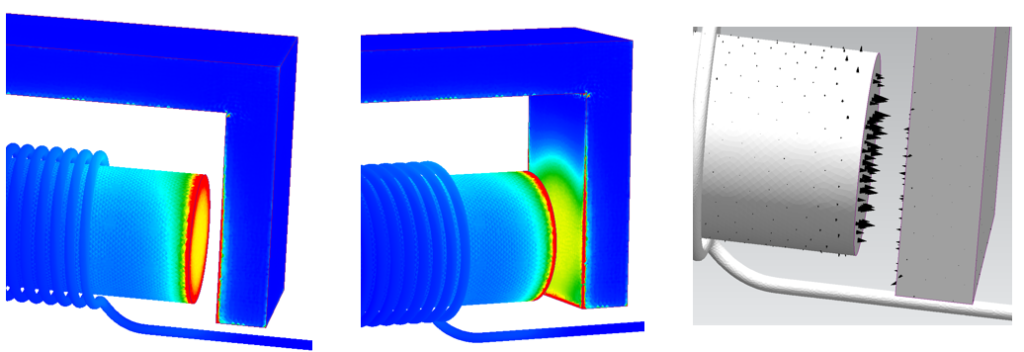
The North pole surface of the core and the South pole face area are now so close to each other so as to be strongly attracted. (As usual, due to the qualitative nature of these demonstration simulations, I’ve left out the legend scale).
Ferromagnetic Cores are Solid
For sure! If the core was made out of rubber then it would deform itself so as to bring the North and South pole faces together. I’m pretty sure rubber isn’t magnetic (can’t be magnetised). So how could some movement be realised in this magnetic circuit? Unlike an electrical circuit that has to have a contiguous geometry for the free electrons to flow, there’s more freedom with a magnetic circuit where the magnetic flux can permeate through air. Breaks, hinges or pivots can therefore be introduced:
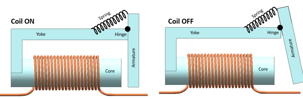
Make the final down piece of the core a separate object (an armature), hinge it to the rest of the core (yoke) and put a spring in that will hinge out the armature when the electromagnet is off. When the electromagnet is on, it will pull the armature towards the core as its force is designed to be stronger that the return force of the spring. The armature can then be used to open or close e.g. a separate electric circuit. The armature doesn’t have to touch the core (and further close the magnetic circuit), it just has to move.
Relay
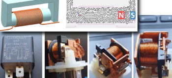
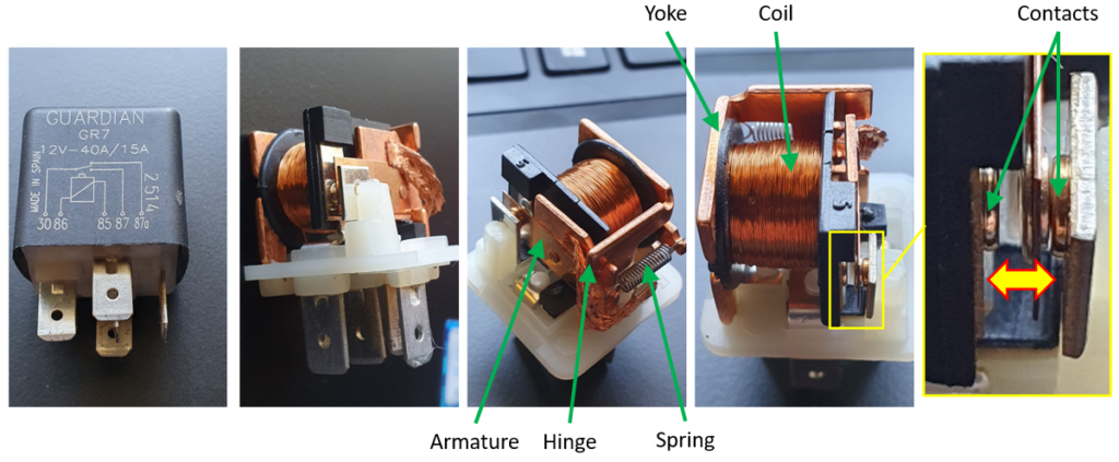
That’s pretty much what a relay is, an electromagnetic switch. They come in various shapes and sizes, but the underlying principle is the same. Here’s an automotive relay. For those that have maintained a car, especially an older one, you might be familiar with them:
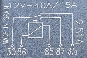
This one’s a 5-pin ‘changeover’ relay. Looking at the circuit diagram on the cover, Pin #30 is the 12V supply from the battery which can be switched (changed over) between the circuits that pin #87 or pin #87a are connected to. All it requires to switch between those 2 circuits is a voltage to be applied over pins #85 and #86 that activates the coil, turning on the electromagnet which in turn moves the armature. The current required to activate the electromagnet is normally much smaller (~0.2A) than the current it is switching (10s of Amps). There is no direct electrical contact between the coil circuit and the circuit(s) that are being switched. A good way to keep the high current/high power electronics away from the more delicate control circuitry of the ECU.
What Does the Magnetic Force Depend On?
It is the strength of the magnetic field (specifically the magnetic flux density, B) that results in the attractive force on the armature. Higher values of B lead to increased magnetic forces. So what does B depend on? For a coil with N turns and length L, carrying a current I:
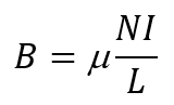
The permeability of the space that the magnetic field occupies is μ. For the design of the relay, where you’d like as small a current I as possible to generate a magnetic field strong enough so as to move the armature and so switch the high current electric circuit, you have some options.
Increasing the number of turns of the coil is the most obvious. Also reducing the length of the coil, or rather the length of the complete magnetic circuit, will concentrate the flux. Then of course you can increase the permeability. Instead of air that has a magnetic permeability almost exactly the same as a vacuum, adding the ferromagnetic core can increase the permeability by many orders of magnitude and thus the magnetic flux density, B. This in addition to its primary use in that the geometry of the core is designed such that the North and South poles can be located very close to each other.
Anecjoke
Richard Feynmann, physicist and Nobel laureate, was asked in an interview on the BBC in 1983 why magnets attract or repel. His response was a wonderful insight into the nature of reality, our ability to describe it and whether we can truly understand it. Here’s a pertinent quote from that interview:
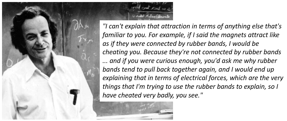
Whereas this blog series attempts to ‘demystify’ electromagnetics, admittedly it still falls very short of providing a complete understanding. However I hope it goes a little further than this 🙂 :