Demystifying Electromagnetics, Part 5 – Ferromagnetic Cores
A coil of wire creates a magnetic field when a current passes through it. The magnetic field is strongest in the middle of the coil. Inserting a ferromagnetic material in the middle of the coil substantially increases the energy stored in the magnetic field. Why, where does this energy come from and can thermal (di)poles help explain?
What is a Pole?
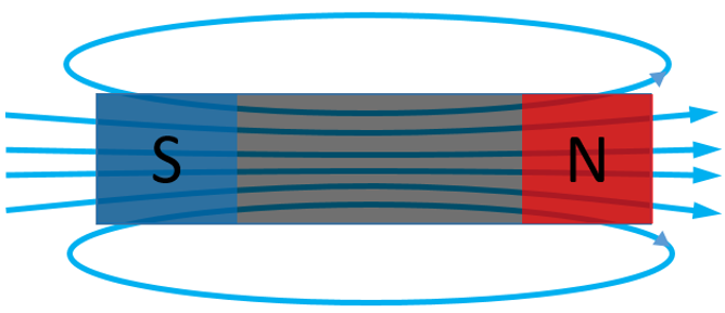
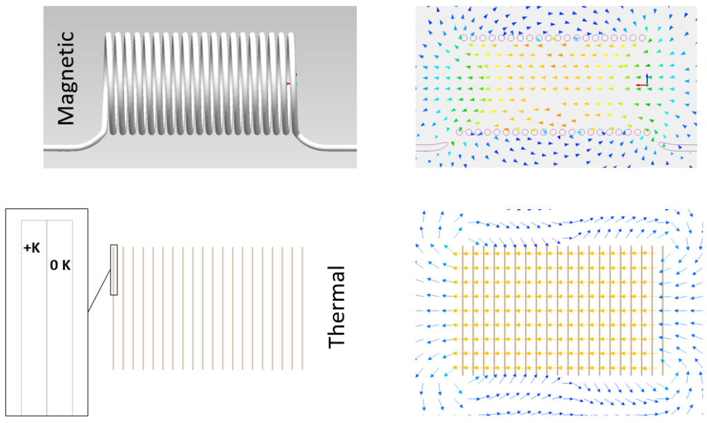
An electromagnetic field, although created by a current flowing round a loop (or loops) of wire, behaves as if there is a positive and negative ‘source’ inducing the magnetic field. Consider these sources as poles. The magnetic field permeates the 2 poles, passing through and looping around them. A permanent magnet’s field is the same, we just name these poles ‘North and ‘South’:
Whereas you can have an electric field generated by a single point charge (a monopole), a magnetic field ALWAYS behaves as if there are 2 poles. There is no such thing as a magnetic monopole!
Strictly speaking the 2 magnetic poles act as if they are so close together that there is no gap between them, i.e. a dipole. The field sinks into one pole and emerges from the other.
Thermal Dipoles
There is a close analogy between magnetic fields and thermal conduction as shown in the following table:
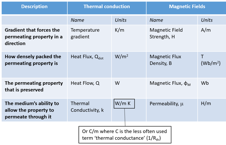
The ability of the medium to allow the property to permeate through it is characterised by its thermal conductivity (for heat flow in thermal conduction) and permeability (for the ‘flow’ of the magnetic flux). When thermal conductivity is defined in terms of a thermal conductance per meter (C/m) its analogy to magnetic permeability (H/m) is evident.
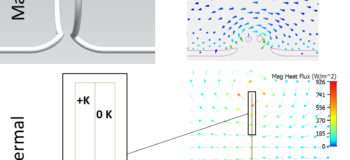
With this direct analogy, is it possible to emulate a magnetic field, thermally? Consider a thermal conduction model where 2 very thin fixed temperature sources abut each other and are placed within a fixed thermal conductivity material. One source has a higher temperature than its neighbour. Heat will flow out of the high temperature source and flow into the low temperature source. Here’s what the resulting animation of that heat flow path looks like when simulated with Simcenter Flotherm:
Heat loops around the 2 slender sources, out of the one with a positive temperature, into the one with a fixed 0 Kelvin.
Close Enough?
Let’s compare that thermal heat flow field with an equivalent magnetic field generated by a single current carrying loop, simulated using Simcenter MAGNET:
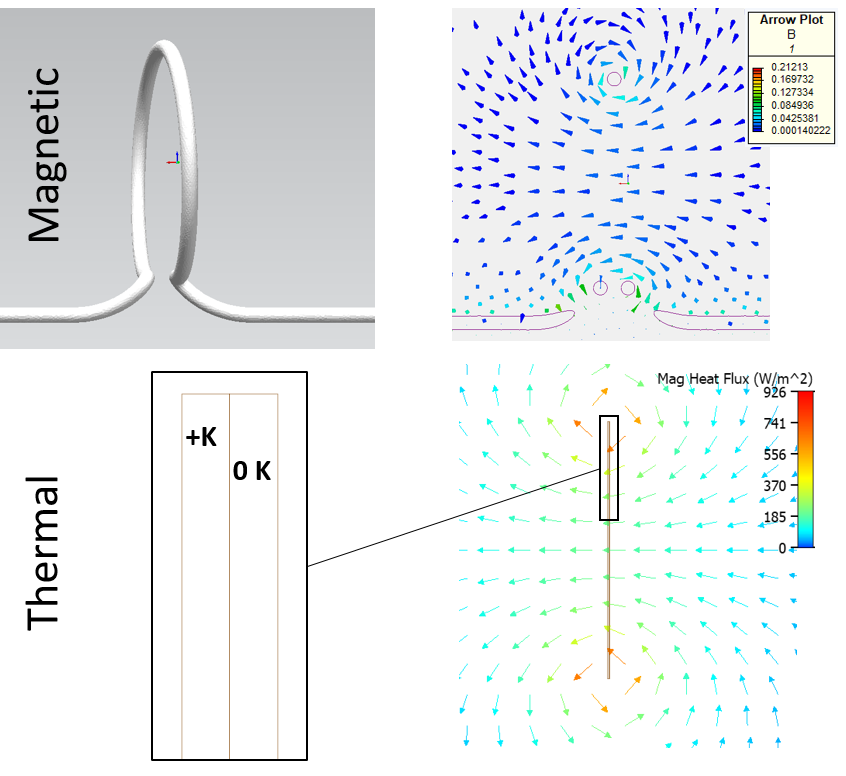
Considering the 2D thermal model is an overly stylised abstraction of the 3D magnetic model, I’d say that the resulting vector fields are close enough to warrant the analogy. The 2 fields permeate in the same way, with Heat Flux (W/m2) being analogous to Magnetic Flux Density, B (Wb/m2) and thermal conductivity (C/m) being analogous to magnetic permeability (H/m).
Thermal Coil?
As we covered in Part 4, a coil of wire is akin to lots of loops of wire placed next to each other. Same is qualitatively true for the thermal equivalent model of a coil inductor:
Just as the coil behaves magnetically like lots of adjacent loops, from a thermal conduction perspective the analogy is multiple thermal dipoles.
What about Ferromagnetic Cores?
A ferromagnetic material is a material that itself becomes magnetised when placed within another magnetic field. When a such a cylindrical core is placed within the coil, the magnetic flux density within that core increases massively. The ferromagnetic material has a magnetic permeability much higher than the air that it is replacing.
Same is true for the thermal dipole equivalent model. The thermal conductivity of the material in the volume occupied by the dipoles can be replaced with a material of much higher thermal conductivity and so the heat flux is increased with it.
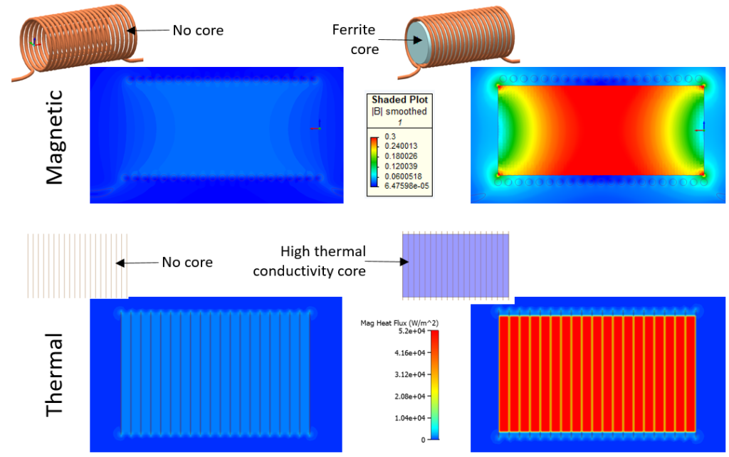
Again, the thermal model dipoles are a little too simplistic an analogy to capture the end effects, but the same increase in ‘flux’ in the cores in both models is evident.
Yes, but Why?
I hope I’ve demonstrated the analogy between thermal conductivity and magnetic permeability, both in terms of their unit definition and through simulation. But why does the ferromagnetic core with its high permeability result in an increase in magnetic flux density and thus energy stored in the magnetic field?
It comes down to superposition. The magnetic field generated by the coil is augmented by the magnetic field generated by the core (that itself is caused by the magnetic field from the coil). As the ferromagnetic atoms with their unpaired outer electrons are aligned by the coil’s magnetic field, their own now aligned magnetic fields are added to the field that caused them. In fact the magnetic field contributed by the core is much stronger than the coil’s magnetic field that ‘triggered’ it.
OK, but Where Does this Extra Energy Come From?
You never get something for nothing. With or without a core, the current flow in the coil for the fixed voltage drop boundary conditions is the same. However the Inductance has been increased, so more energy can be stored and it would take much longer for the coil to reach a steady state. It’s that increased ‘magnetic field charging time’ which is the price to pay.
The following Simcenter MAGNET simulation compares the transient response of the coil, with and without a ferromagnetic core. The colour plot is of the magnetic flux density, B.
At the end of the response to an applied fixed voltage drop, the current assumes a constant value, irrespective of whether there’s a core or not. As shown in Part 4, the inductance of a device is such that it will delay the establishment of the current flow. By adding a ferromagnetic core, the inductance is increased and so it takes longer for the current flow to establish (there is more of a lag between a change in voltage and the corresponding change in current).
In addition, the amount of energy that magnetic field ends up storing is also much greater, and takes longer to establish, when there is a core compared to when there isn’t.
Anecjoke
I replaced my driveway last year, backbreaking work but very rewarding. Before laying a gravel top layer I dug a French drain to ensure the driveway did not get waterlogged in the famously wet English weather.
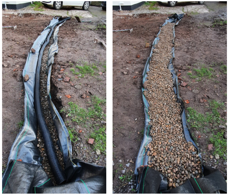
From a geological fluid flow perspective, ‘permeability’ is a recognised parameter that determines how easily a fluid can flow through a porous media such as subsoil. By replacing the subsoil with a perforated pipe surrounded by gravel, the permeability is massively increased and the fluid mass flow rate within the drain will be much higher than its surroundings.
Considering the same word ‘permeability’ is used to both describe the ability of a material to permeate a magnetic field and allow for a fluid flow through it, this magnetic-hydro analogy could have been used instead of the magnetic-thermal analogy above. However from a magnetic perspective air has a very low permeability, from a fluid flow perspective air has a very high permeability!