Demystifying Electromagnetics, Part 4 – Inductors
Welcome to Part 4 in this blog series that hopes to demystify electromagnetics for those of you who might have a background in mechanical engineering, fluid flow and heat transfer. In the previous 3 Parts we’ve covered some basic building blocks of the EM world. Not covered as deeply as you’d expect to in academia, but with the intention of providing you with at least an intuition, at most a working knowledge, of the physics of EM. Less equations, more analogies and a surplus of pictures and animations is the motto for this series! Ultimately we’ll be getting onto electric motors, generators, induction cooking, levitation, loud speakers etc. etc. but for now some more basics – Inductors.
A Loop is Better than a Wire
As we covered in Part 3, moving charges create a magnetic field that loops around them. If those charges are moving in a wire, and the wire is looped, then the magnetic field inside that loop is intensified as the (blue) magnetic flux lines fold in on each other, increasing the magnetic flux:
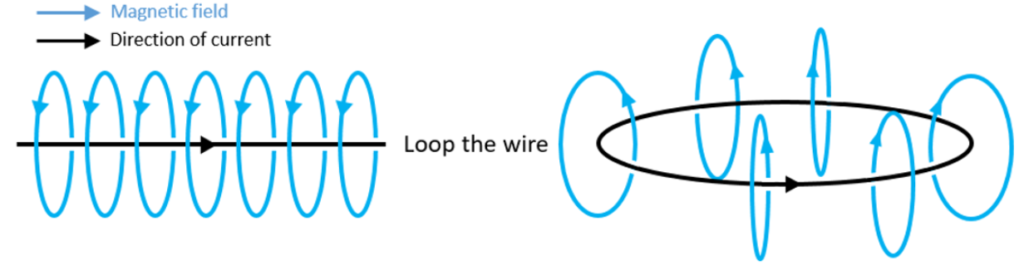
A Coil is Like Lots of Loops
To feed current into a loop, the loop would have to be terminated by individual wires leading to a battery, or some other source of current. Consider a coil of wire though, with wire terminals on each end of the coil. Each turn of the coil is akin to an individual loop. The coil itself is akin to lots of loops stacked on top of each other. The resulting magnetic field is a superposition of the individual loop magnetic fields:
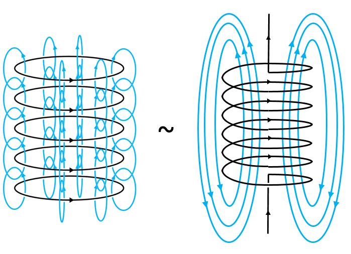
A coil is the most common form of an electromagnet, a magnetic field that is created due to a current. Sure, even an individual wire carrying current acts as an electromagnet, it’s just that when you loop the wire and stack the loops on top of each other does the magnetic field from each loop combine to form a strong magnetic field. (Adding a ferromagnetic material in the core of the coil further enhances that magnetic field, but more on that in the next blog).
The Magnetic Field Stores Energy
Just like a gravitational field, a magnetic field stores energy, potential energy with the potential for that energy to be utilised. The magnetic field is defined in terms of a magnetic flux measured in Wb (Weber). It is this property that, although not flowing, is conserved in the same way that a heat flow (Watt) is conserved.
Let’s revisit our analogy table to further compare heat flow and magnetic fields:
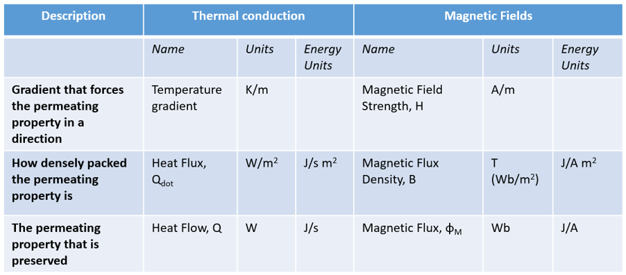
As before, the term ‘permeating’ is used in lieu of ‘flowing’ to describe both thermal conduction and magnetic fields. There is analogy enough to warrant the use of a single term!
From a thermal perspective, what flows, what is conserved, are Watts. From a magnetic perspective it’s Webers. Just as a heat flux describes the ‘density’ of the flow in terms of W/m2, the magnetic flux density is measured in Teslas (which are Wb/m2). It is somewhat confusing to see the terms flux and flow used differently for thermal and magnetic descriptions, I blame history.
The above table also shows the units for these properties when expressed in terms of energy (Joules). For heat flow it’s J/s. For the magnetic flux it’s J/A. Given that it is a current I (Amps) that creates the magnetic field, the magnetic flux is how much energy is stored in that field per Amp that was used to create it.
Inductance is all About Energy
So if the magnetic flux is a form of stored energy, what measure can be used to quantify how well a conductor stores energy in its magnetic field?
Answer: Inductance
The inductance (L) of a device is defined:
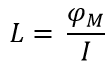
By ‘how well’ we mean that for a given current I flowing through the conductor, how much energy then exists in the resulting magnetic flux φM. If say there are many coil loops and/or if the loops have a big radius, then the Inductance will be higher, there will be more magnetic flux and thus more energy will be stored in the magnetic field.
‘Inductance’ in that energy is ‘induced’ out from the current flow, into the magnetic field. The inductance is measured in Henrys (H), which are equivalent to Wb/A and from an energy perspective J/A2.
Induced Energy Comes at a Cost
The current flows in a conductor due to the electric field (V/m) that is imposed across the conductor due to attaching the conductor a battery. That electric field is also a form of potential energy. That energy ‘fuels’ the creation of the magnetic field. How well the magnetic field ‘steals’ energy from the electric field in the conductor is the Inductance. However this energy thievery comes at a cost.
If you ignore the Inductance, then say you apply a fixed voltage drop across a conductor, the current will flow instantaneously.
If the conductor has an Inductance (due to it being coiled so as to condense the magnetic field) then as soon as a fixed voltage drop is applied over the conductor, the conductor will steal energy from the electric field and dump it in its magnetic field. This acts so as to delay the establishment of the current flow.
There is a lag between the change in the imposed voltage change and the resulting steady stating of the current flow. Inductors are sometimes called ‘chokes’ for exactly this reason.
Newton’s 3rd law states that every action has a reaction, inductance is an example of this. The instantiation of the magnetic field by the current flow works against the current flow that is creating it (rather it works against the electric field that is forcing the current to flow). Classically this is described by one of the Maxwell equations, the Maxwell–Faraday equation for induction:
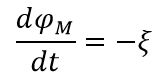
ξ is the force (electromotive force, EMF) that is generated whilst the magnetic flux changes in time.
Its sign is negative indicating that it works against the voltage that generates the current that generates the magnetic field. But only when the magnetic field is changing in time, a purely transient response behaviour. This ‘back EMF’ effect is more commonly known as Lenz’s Law.
A reactant force / a thieving of energy are, in my mind, 2 approaches that describe the same effect.
A Turbine is Analogous to an Inductor
Considering this blog series is targeted at Mechanical Engineers who might want to get a sense of electromagnetics, I’ll continue to use fluid analogies as far as possible.
As described in Part 2, a current flow is just a charge flow rate, analogous to a mass flow rate of a moving fluid. A wire conductor is analogous to a pipe with fluid flowing through it.
Instead of equations (of which I have included maybe too many in the above), let’s imagine a turbine placed inside that pipe and a fixed pressure drop imposed on the end of the pipes:
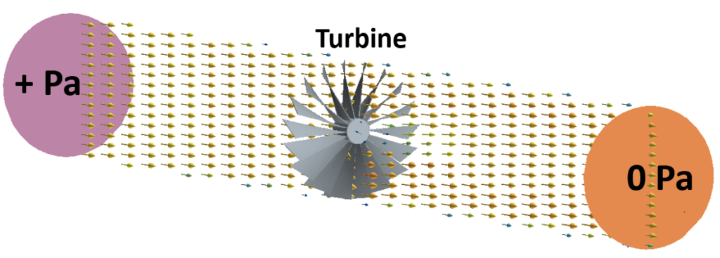
The fluid will start to flow at time = 0s. As the fluid starts to flow some of its energy will be taken by the turbine as the turbine starts to spin due to the fluid forces exerted on it. As it spins up it takes more energy from the fluid, reducing the rate at which the fluid flow would otherwise establish itself (compared to the turbine not being there).
At some point an equilibrium is established where the turbine rotation is congruent with the fluid flow that is passing through it.
It is the moment of inertia of the turbine around its flow aligned axis that dictates how much energy it can take from the fluid flow as a function of the fluid flow rate passing through it and thus how long it takes for the fluid flow to achieve an equilibrium with the turbine rotation.
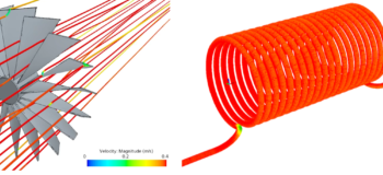
Here’s an animation, modelled in Simcenter, of the spin up of the turbine and graphs indicating the rate at which the flow rate and the energy stored in the turbine reach equilibrium:
An Inductor is Analogous to a Turbine
Instead of a pipe carrying a fluid, consider a wire carrying a current. Instead of a fixed pressure drop, we have a fixed voltage drop. Instead of a turbine, we have the wire coiled:
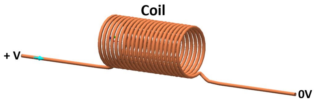
Just as the turbine’s moment of inertia delayed the flow reaching equilibrium, the coil’s inductance delays the establishment of the current flow:
The left hand animation shows the current density J building up over time. The right hand animation shows the formation of the Magnetic field, not in terms of its flux φM, but by its flux density B, φM/m2 (= Tesla).
The inductance of the coil (a function of its geometry) is its capability to store a certain amount of energy in its magnetic field given a current that is creating it. When all that energy has been ‘stolen’ from the electric field, the current stabilises and the total amount of energy stored in the magnetic field does not change.
Energy Analogy
Note how the graphs of inductor energy and magnetic field energy vs. time are so alike. The energy stored within a rotating mass (e.g. turbine) and an inductor (e.g. coil) have analogous definitions:
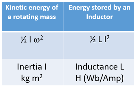
The rate of rotation w (rad/s) is itself related to the flow rate which is analogous to the current. The inertia is analogous to the inductance. Despite the former being associated with kinetic energy and the latter with potential energy, their formulations are the same.
Although analogies only go so far, and they do tend to break down when you get into specifics, they are a useful tool when introducing a new subject when an existing subject is already understood.
Anecjoke
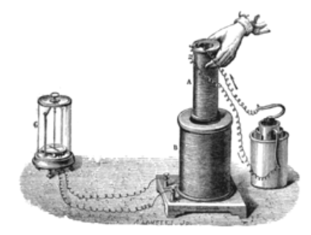
I described the term ‘inductance’ as how well an electrical device can ‘induce’ energy from its own changing electric field, that gives rise to the current flowing through it, into its own magnetic field. However this wasn’t the original intention of the term ‘inductance’. Faraday’s original experiment on August 29, 1831 showed how the magnetic field from one coil with a current passing through it could ‘induce’ a current flow in another passive static coil, but only as the smaller coil was being inserted into the larger coil. As far as the larger coil was concerned, it experienced a changing magnetic field from the smaller coil as the smaller coil moved into it. Thus, an EMF was induced in the larger coil causing its free electrons to move, i.e. a current to flow.
So, a current can be induced in another device when it experiences a magnetic field that changes in time (mutual inductance). Or a varying current can be delayed in a given device due to its own magnetic field that changes in time (self inductance).
Not much of an anecdote, more a comment. By way of apology I’ll leave you with this limerick:
A friend who’s in liquor production,
Has a still of astounding construction,
The alcohol boils,
Through old magnet coils,
He says that it’s proof by induction.


