Embeddable BCI-ROMs, Taking Electronic Thermal Simulation to the Next Level, a Personal Perspective
Innovations in the thermal simulation of packaged semiconductor devices can be traced back over 30 years. The recent release of Simcenter Flotherm 2310 heralds the latest such innovation in the form of Embeddable BCI-ROMs. A step change in the ability to accurately predict the thermal performance of modern electronics, Embeddable BCI-ROMs are the latest in a long line of capabilities that we’ve delivered to help better serve the electronics thermal industry.
THERMINIC (Thermal Investigations of ICs and Systems) is an annual European conference that’s been running since 1995. At the 2014 workshop in the UK I was lucky enough to see the presentation, by Professor Lorenzo Codecasa from the Politecnico di Milano, of his and his colleague’s seminal publication titled ‘Fast novel thermal analysis simulation tool for integrated circuits (FANTASTIC)’. As with many innovations, it’s the pollination between adjacent disciplines where opportunity lies. Professor Codecasa, coming from an electrical engineering background, applied his deep mathematical knowledge to the field of electronic thermal simulation to demonstrate a Krylov based model order reduction approach tailored to thermal conduction applications. To better appreciate the unique value of that approach, it is best considered in the context of the state of the art in electronic component thermal simulation up to that point.
Electronics Thermal Simulation Mostly Involves Component Temperature Prediction
When designing an electronics product, or a product that contains electronics within in, the operating temperature of electronic components (packaged semiconductor devices) can be taken as a leading indicator of reliability. Too hot and they are more likely to fail. Conversely too cold and you’re not fully capitalizing on the functional capability of those components. Prediction of component temperature, as part of a simulation enabled virtual prototyping design process, is therefore key.
There are 2 temperatures that are commonly considered, with maximum rated temperatures specified by an e.g. Tier 2 component supplier:
- Junction temperature. This is the temperature of the semiconductor chip itself, commonly the hottest temperature within the component.
- Case Temperature. This is a peripheral surface temperature of a component, normally on the face that has a heatsink attached.
The question then is ‘how do I thermally model electronic components so as to predict either of these 2 temperatures?’. There are 2 main issues that someone wishing to perform electronic thermal simulation of packaged semiconductor devices face:
- The devices are really really complex. There are nano-scale semiconductor features, micro-scale electrical circuitry and the package in which these are placed is constructed from a range of constituent materials, none of which are well characterised in terms of knowledge of their thermal material properties.
- A supplier of electronic components, to protect their IP, will (understandably) not be willing to provide a detailed description of the internal construction of their devices to their customers.
The Simplest of Modelling Approaches
When faced with nothing but the data that’s available to you, the simplest thermal modelling approach is to assume that the component is a single lumped material. The outer size and shape of the component is well known, isn’t considered IP (obviously) so all you then need to do is to create a solid object of that size and shape and assign an appropriate material to it. But what material properties to use?
For steady state thermal simulation you need only to assign a thermal conductivity (W/mK). For transient simulation you need also to assign a Specific Heat (J/kgK) and a Density (kg/m3), or at least the correct product of these 2 parameters.
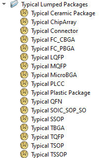
To address this need, we created and validated a ‘Typical Lumped Packages’ material library where all that’s required is knowledge of the package style.
With such a simplistic modelling approach, the most that can be expected, and the most that is supported by our Typical Lumped Packages material library, is an indicative Case Temperature prediction.
Equivalent Thermal Circuits – ‘2-Resistor’
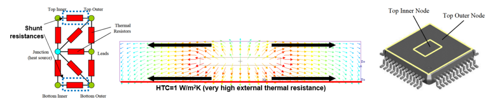
‘Obfuscation‘ is a very appropriate term when it comes to the requirement for a supplier to protect their component IP. The use of equivalent thermal circuits (networks) as a way to describe the heat flow paths and thermal resistances is one way of achieving obfuscation but still considered as a predictive model. ‘Equivalent’ in that we’re talking thermal here, not electrical, but the electro-thermal analogy holds well.
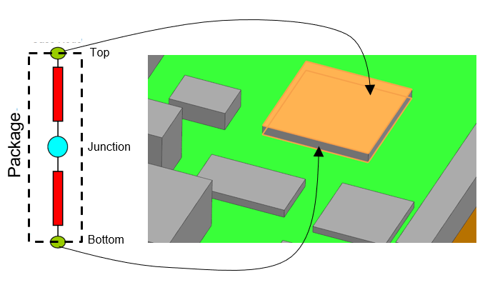
The thermal network model (equivalent thermal circuit), when embedded within a 3D simulated environment, and when a power assigned to the node that represents the chip junction, has the ability to predict 3 temperatures: Junction, Top, Bottom. Either the Top or Bottom nodal temperature might be considered the case, depending on package style. Important to note though that without consideration of any nodal thermal capacitances, this model is just valid for steady state simulation.
The JEDEC JESD15-3 standard documents the approach by which these ‘2R’ models can be extracted. For inclusion in a 3D conjugate heat transfer simulation in tools such as Simcenter Flotherm the component shape is still required, but beyond that just 2 thermal resistances (K/W) are needed, the detailed internal package construction has been obfuscated.
Equivalent Thermal Circuits – ‘DELPHI’
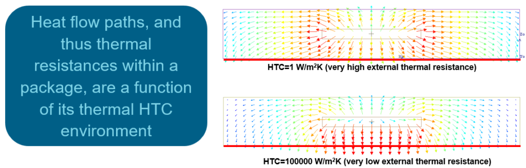
The problem with the 2R approach, despite its attractive simplicity, is that its predictive accuracy does not hold for all thermal operating environments that the model is placed in. ‘Thermal environment’ can be taken as the heat transfer coefficients (HTCs (W/m2K)) that the peripheral faces of the package are subjected to. If the operating HTCs that the 2R model is subjected to differ compared to those that were imposed when the 2R model was extracted, then the 2R model predictive accuracy will be majorly impacted.
Its accuracy is said to be dependent on these package boundary conditions. What is desired is for a thermal model whose accuracy is said to be independent of these boundary conditions, i.e. it is ‘boundary condition independent’ or ‘BCI’ for short.
The EU collaborative ‘DELPHI’ project ran from 1995 to 1997. It was led by Flomerics, the company to first develop and release Simcenter Flotherm, subsequently acquired by Mentor Graphics, more recently acquired by Siemens (I’m happy to say a journey that has covered my entire career). The motivation of DELPHI was to elaborate an approach whereby thermal models of electronics components might be extracted by component suppliers, obfuscating IP, but still demonstrating BCI accuracy.
Although many consider the DELPHI thermal modelling approach to be just an equivalent thermal circuit topology, it was as much a methodology to extract any topology, so long as it was verified as being BCI.
Prior to 1994 the state of the art was to consider at most star networks (of which 2R was a subset). Accommodation only of a 1D flow of heat away from the heat source, in 1 or more directions. With such a network topology there is no allowance of the subsequent cross interaction of those heat flow paths as occurs as a function of the environmental HTCs the heat flow experiences when it encounters the periphery of the package.
This all changed thanks to Clemens Lasance, the first ever Simcenter Flotherm user, a pivotal figure in the DELPHI project and in the evolving electronics thermal community from the ’80s to the 2000s, and now Philips Research Emeritus. Clemens faxed Harvey Rosten (co-founder of Flomerics) in June 1994 proposing the inclusion of shunt resistances (‘surface-surface links’) in a thermal network topology to account for these boundary condition dependent effects.
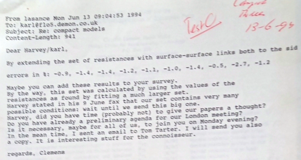
The following year this seminal SEMI-THERM paper was published and the viability of compact thermal modelling underwent a step change as a consequence:
The key to the DELPHI approach was indeed accommodation of these shunt resistances in the thermal circuit, to allow for the difference in internal spreading resistances the heat flow experiences as a function of the operational HTCs a package might be subjected to.
The DELPHI approach was standardized by JEDEC as JESD15-4 in 2008.
There were 2 follow-on projects from DELPHI, namely PROFIT and SEED. Although PROFIT demonstrated a method to extend the DELPHI thermal resistor network topology to accommodate thermal capacitances at optimised locations between network nodes (and therefore allow for transient application) such an approach was not further adopted or standardised.
BCI-ROMs to Address DELPHI Model Deficiencies
For sure DELPHI models are better than 2R models in that they demonstrate BCI behaviour, but they still fall short of the needs of the electronics industry today in 2 key areas:
- DELPHI models (despite the PROFIT project recommendations), and 2R, are limited in that they only consider thermal resistances, not capacitances. They are therefore not appropriate for being used for transient simulation.
- Both DELPHI (commonly) and 2R models (always) consider only a single Junction node and so do not satisfy the needs of multi-chip modules, system-on-chips, heterogeneous chiplet architectures etc. designs.
Whereas simulation of monolithic packages (containing a single chip) under steady-state conditions was good enough 20 years ago, the needs of the electronics industry today has evolved well beyond that constraint. To ensure reduction in over-design, by considering usage profiles, flight, mission or drive cycles directly, and requiring accommodation of advanced multi-heat source packages, a more encompassing component thermal modelling approach is necessitated.
In theory the DELPHI methodology might be extensible to cover multi-heat source applications, but with its objective function optimisation fitting approach, this doesn’t scale well enough for anything more than a handful of heat sources. This publication by John Janssen from NXP and Professor Codecasa at the 2015 THERMINIC workshop very well demonstrates that fact.
Enter BCI-ROMs as a Panacea
The mathematical approach that Codecasa presented back in 2014 as his ‘FANTASTIC’ method ticks all the necessary boxes:
- an approach by which a BCI model might be extracted
- can accommodate multiple heat sources
- is transient simulation compliant
- and (and as an added bonus) can have its accuracy prescribed a priori to its extraction
The mathematics is a bit heavy, to say the least. It’s a Krylov subspace projection based model order reduction method that entails the use of Singular Value Decomposition, Eigen value determination plus a range of other very specific functions. Point being that the implementation of the method is extremely robust and fully automated to the extent where a Tier 2 component supplier can simply press a button to have a BCI-ROM extracted.
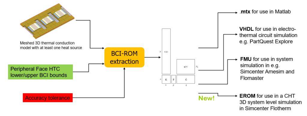
BCI-ROM Input Requirements
A BCI-ROM is extracted from a supplied 3D ‘detailed’ or so-called ‘full order model’. This is the type of model that you would otherwise create for simulation purposes, were you to have access to all the required data, which is exactly what the Tier 2 component supplier has access to.
A lower and upper bound of HTCs, between which the BCI-ROM is extracted to be accurate within, is defined as input. Anything from order 1-10 W/m2K that would represent natural convection cooling environments all the way up to order 100000 W/m2K that would represent some form of direct or indirect liquid cooling.
Unlike the equivalent thermal circuit modelling approaches, where the resulting accuracy has to be determined after extraction, a BCI-ROM can be extracted to a given input accuracy tolerance. Of course the tighter the tolerance, the longer the extraction takes, but that’s to be expected and would only be suffered once.
A BCI-ROM is a Collection of Matrices
Once extracted, a BCI-ROM is simply a collection of matrices. A thermal conductance matrix, a thermal mass matrix, a matrix that enables physical temperatures to be reconstructed from ROM space temperatures. As indicated, the mathematics is quite complex but suffice to say the ROM matrices are much much smaller than the input detailed (‘full order’) model matrices, are therefore extremely fast to solver (up to e.g. 1e4 times faster), hide proprietary IP yet can be solved with a basic ODE (Ordinary Differential Equation) solver.
BCI-ROM Export Options
The BCI-ROM matrices can be exported from Simcenter Flotherm in a number of different formats, each one appropriate to the downstream simulation tool that might ingest them. .mtx for use in Matlab or Octave, VHDL for use in a range of electro-thermal circuit simulators, wrapped up in an FMU container for use in system simulation tools and finally, new to Simcenter Flotherm 2310, exported as an ‘EROM’ (an Embeddable BCI-ROM) to be reinserted into a Simcenter Flotherm system level 3D CFD and thermal environment model.
Prescribed vs. Simulated HTCs
It was once described to me by Clemens Lasance that the fundamental value of CFD for electronics cooling applications is as an HTC predictor, as a way of simulating, as opposed to assuming or prescribing HTCs. These HTCs occur and vary due to the physics of the efficiency by which heat is extracted from a hot solid surface. This might be due to natural convection, forced convection, the placing of a block of metal on a component or even the immersion of the component within a dielectric fluid bath. All these examples result in a sequential increase of the environmental HTCs that are imposed upon them (i.e. a sequential decrease in the thermal resistance the heat experiences after it flows out from a packaged semiconductor device to its ambient temperature environment).
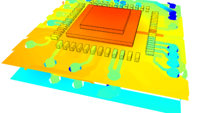
3D CFD is the only way to simulate these environmental HTCs and, as such, the ability to include an obfuscated, IP protected, transient compliant, multi-heat source accommodating, Embeddable BCI-ROM within a 3D CFD simulated thermal environmental really is taking electronics thermal simulation to the next level. More details of which are available in this blog about the recent release of Simcenter Flotherm and this one that focuses more specifically on the EROM capability.
At the Interface of Industry and Academia
Innovation rarely happens in isolation.
Conferences such as THERMINIC are a golden opportunity for industry to interact and liaise with academia. Not a ‘give and take’ relationship, but a partnership where the needs of industry can be communicated to academia whereby an iterative approach to reconciling evolving industrial needs with the novel technologies that academia are developing, might be married together for the benefit of all.
If it wasn’t for Professor Codecasa’s efforts and presentation at THERMINIC in 2014, Clemens Lasance’s subsequent Keynote endorsement and support of that technology, John Janssen’s preliminary evaluation of the FANTASTIC method and other alternative approaches, Siemens’ sponsorship and attendance of THERMINIC, Janssen’s recommendation for us to see his and Lorenzo’s subsequent THERMINIC presentation in 2015, maybe we would have missed this opportunity. But we at Siemens didn’t. We then embarked on a successful collaboration with Professor Codecasa and now, as a consequence, Embeddable BCI-ROMs are commercially available in Simcenter Flotherm with all of the industrial benefits described above.
Industry and academia together can do more together than either can do separately. The Embeddable BCI-ROM story is just one example. I hope and believe there will be many more to follow.