How TotalEnergies Improves EV Fast Charging with Immersion Cooling
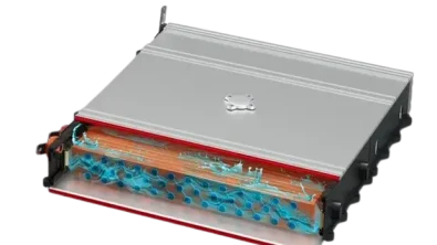
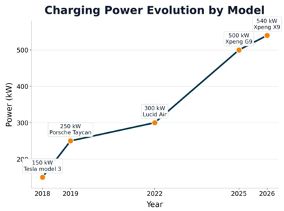
The race toward faster electric vehicle charging is not just about charger infrastructure or voltage level; it is also a thermal management challenge. As peak charging power climbs from 150 kW on early Tesla Model 3 units to over 500 kW on the latest Xpeng, the heat generated inside the battery pack scales in proportion. Managing that heat efficiently is what separates a 10-minute charge from a battery that throttles itself to stay thermally safe.
At Realize LIVE Europe 2026 in Amsterdam, Jérôme Jeanclos from TotalEnergies presented a case study that answers the following question: Does direct immersion cooling of electric vehicles battery pack outperform conventional indirect liquid cooling, and by how much? The answer, derived using Simcenter Amesim, is both quantified and actionable.
The Fast Charging Thermal Management Problem
Every watt of charging power that enters a lithium-ion cell produces waste heat. At high C-rates, internal resistance losses rise sharply, and the battery management system (BMS) may need to derate charging current the moment cell temperatures approach their upper safety limits, typically around 45-50 °C mean cell temperature.
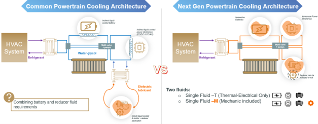
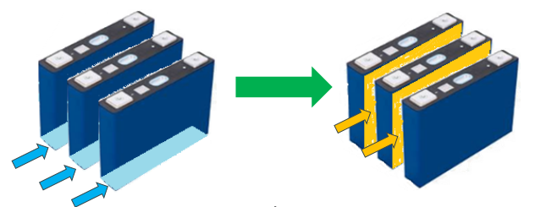
Current battery pack architectures use indirect liquid cooling: a water-glycol circuit flows through a cold plate bonded to the bottom or side of the battery module or pack. A thermal interface material (TIM) bridges the gap between cell cans and the cold plate. This approach works, but it introduces a stack of thermal resistances and a thermal gradient across the cell surface, which limit how efficiently heat can be extracted.
Direct immersion cooling removes those resistances and gradients. Cells are submerged in a dielectric fluid that contacts the cell can surface directly. The thermal resistance collapses because there are no intermediate layers and the heat exchange area increases dramatically. TotalEnergies set out to quantify this advantage through a multi-scale simulation campaign.
Architecture Study: from Fluid Selection to Full Vehicle Simulation
The study was structured in two complementary layers that reflect the hierarchy of engineering decisions.
Layer 1: Fluid Selection and Optimization
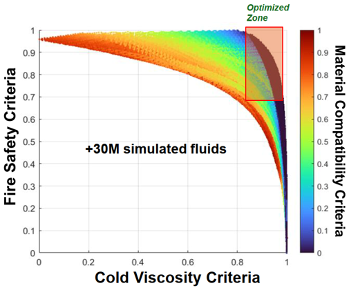
Before any thermal simulation, TotalEnergies ran a large-scale fluid screening exercise. Using a multi-criteria optimization framework, the team evaluated over 30 million simulated fluid candidates against seven simultaneous requirements:
- Thermal properties (specific heat capacity, thermal conductivity, density)
- Cold-temperature viscosity (critical for pump sizing at low ambient temperatures)
- Thermal runaway mitigation capability
- Material compatibility (copper corrosion resistance)
- Fire safety criteria
- Aging and oxidation stability
The outcome was a Pareto-optimal fluid formulation that satisfies OEM-level constraints for a single fluid architecture: one dielectric fluid shared across the battery, power electronics, and (optionally) the e-motor reducer. This eliminates the separate water-glycol and dielectric lubricant circuits present in today’s multi-fluid powertrains, reducing system complexity and weight.
Layer 2: Thermal Simulation at Battery and Vehicle Level
With the fluid selected, the simulation campaign proceeded in two stages using Simcenter Amesim.
Battery-level model: A prismatic NMC 77 kWh pack was modelled under steady-state assumptions (uniform heat generation, uniform flow distribution).
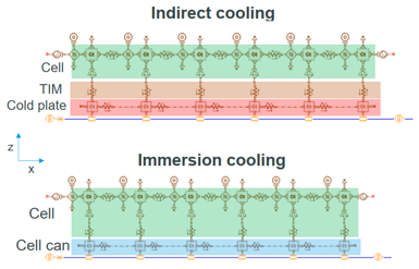
The 1D thermal resistance network was validated against a full 3D CFD simulation, confirming desired accuracy for cell and pack temperature spread:
| ΔT cell 3D CFD | ΔT cell 0D | ΔT avg 3D CFD | ΔT avg 0D | ||
|---|---|---|---|---|---|
| 5 L/min | ref | -10% | ref | +0.2°C | |
| 20 L/min | ref | -8% | ref | +0.3°C |
Vehicle system model: Three cooling architectures were built and simulated, all calibrated on Tesla Model Y component data to ensure realistic boundary conditions:
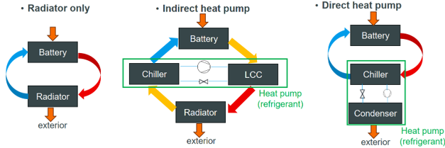
Each architecture was simulated with both indirect cooling (water-glycol through cold plate) and direct immersion cooling (dielectric fluid in contact with cell cans), yielding six system configurations in total.

The Neural Network Acceleration Strategy
A full-vehicle thermal model integrating battery cells, radiator, centrifugal pumps, chiller, condenser, and heat pump is computationally expensive. This prevents running effectively large Design of Experiments given the short timeframe of the project.
TotalEnergies solved this with neural network surrogate models created in Simcenter Reduced Order Model and embedded within the Simcenter Amesim environment. Two key components were replaced by trained neural networks:
– Radiator: A detailed fin-and-tube heat exchanger model with aeraulic and hydraulic transfer was replaced by a neural network taking fluid flow rate, air velocity, inlet temperatures, tube geometry, and fluid thermal properties as inputs and predicting heat rejection power as output.
– Heat pump (plate heat exchanger (chiller and LCC) + compressor): A multi-input neural network replaced the full refrigerant cycle model, predicting compressor work, electronic expansion valve operating point, saturation temperatures, and heat exchange powers at both the chiller and liquid cooled condenser.
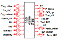
For the whole model simulated over a driving cycle, a ×160 speedup was observed with no meaningful loss of accuracy, as exemplified by the correlation between neural network and Simcenter Amesim chiller heat exchange results.
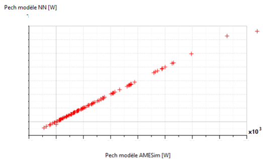
This approach enables parametric sweeps and architecture trade-off studies that would be slower with brute-force simulation.
Results: Quantifying the Immersion Cooling Advantage
Battery-Level Performance
At the battery level, the comparison between direct dielectric cooling and indirect water-glycol cooling reveals a clear thermal advantage for immersion:
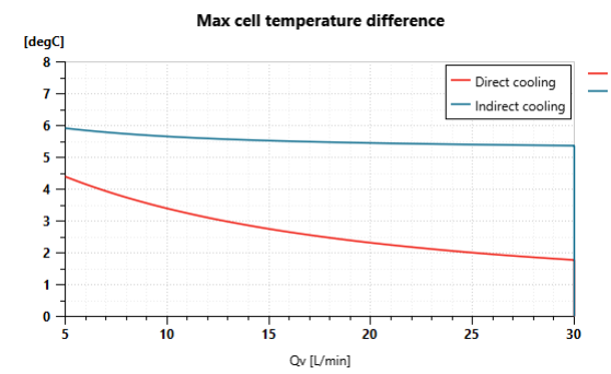
– Maximum cell temperature spread: Direct cooling reduces maximum cell delta temperature by approximately 2 °C across the full flow rate range (5–30 L/min).
– Mean cell temperature: At 15 L/min, direct cooling reduces mean cell temperature by 3 °C, corresponding to a +50% improvement in cooling efficiency at that operating point.
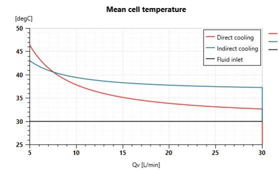
This is not a marginal gain. A 3 °C reduction in mean cell temperature directly translates into higher allowable C-rates before the BMS derates charging current.
Vehicle System-Level Performance: Maximum C-Rate
The vehicle-level key performance indicator is the maximum C-rate achievable while keeping mean cell temperature below 50 °C. Results across all six configurations are shown below:
| maximum C-rate | Indirect cooling with water glycol (ref) | Immersion cooling with dielectric fluid | Indirect cooling with dielectric fluid | Immersion cooling with water glycol |
|---|---|---|---|---|
| Radiator only | 1.12 | 1.21 | 0.91 | 1.57 |
| Indirect heat pump | 1.57 | 1.71 | 1.29 | 2.07 |
| Direct heat pump | 2.25 | 2.41 | 2 | 2.73 |
Switching from indirect to direct immersion cooling in a direct heat pump architecture raises the maximum C-rate from 2.25 to 2.41, an ~8% reduction in theoretical minimum charging time, without requiring any redesign of the pump or heat exchanger.
The analysis also reveals that the cooling method effect dominates the fluid properties penalty. Dielectric fluids have lower specific heat capacity, thermal conductivity, and density than water-glycol, properties that reduce heat exchanger efficiency downstream. Yet the superior thermal contact at the cell level more than compensates: the net system-level result still favors direct immersion. This is a non-obvious conclusion that only a full system simulation can surface.
What This Means for Next-Generation EV Powertrain Design
For powertrain engineers and OEM thermal architects, the practical takeaways are:
1. Immersion cooling is not just a battery-level improvement, its advantage propagates to improve the fast charging capabilities, where it matters most for customer experience.
2. Fluid property penalties are real but manageable, system-level simulation is essential to avoid over-penalizing dielectric fluids based on component-level metrics alone.
3. Single-fluid architecture simplifies the powertrain, eliminating separate water-glycol and lubricant circuits reduces component count, sealing interfaces, and thermal management control complexity.
4. Neural network surrogates in Simcenter Amesim enable fast design space exploration, a ×160 speedup opens the door to optimization loops and sensitivity analyses that are otherwise out of reach.
5. Immersion cooling also enhances battery safety. Beyond improving heat extraction during charging, direct immersion cooling provides a thermal buffer around the cells and can help limit thermal propagation in the event of a cell failure. Combined with dielectric fluids, immersion cooling architecture therefore offers an additional lever for thermal runaway mitigation and pack-level safety.
Presented by Jérôme Jeanclos (TotalEnergies) at Realize LIVE Europe 2026, Amsterdam, June 30, 2026.
Want to try Simcenter Amesim yourself?