The Key to Easier Thermal Assessment of Engine & Gas Turbine Blades
Building a digital twin of a gas turbine is a complex endeavor that traditionally takes months to accomplish. There are many components, physical factors, and interrelationships to consider. The gas turbine operates under high temperature, pressure, and loading, which presents challenges in ensuring that the system works safely and effectively. Different teams need to work together to achieve their respective design goals while respecting both their own constraints as well as those of other teams. For example, the thermal team must be mindful of stress and displacements. The structural team must also be mindful of the thermal-induced stresses and changes in material properties.
Working with major gas turbine manufacturers, we have developed over the years within Simcenter 3D an integrated solution for end-to-end thermo-mechanical simulation of turbomachinery. This solution integrates multiple physics disciplines within a single environment to create a whole engine model. It also helps streamline the multiphysics analysis and efficiently simulate the interrelated effects of heat transfer, fluid flow and structural mechanics, e.g., through specialized convective boundary conditions associated with the geometry or a condition sequence manager.
Simcenter 3D Thermal Multiphysics 2021.2 will include several great enhancements for turbomachine analysis to determine the most effective blade cooling strategy for your design.
Immersed Ducts
As the turbine entry temperature increases so does the gas turbines’ thermal efficiency. However, high temperatures can damage the turbine, as the blades are subject to large centrifugal forces. Additionally, the materials are weaker at high temperature and more prone to creep. This means that turbine blade cooling is essential.
The design, modeling and optimization of the cooling channels and, in particular, of the many very small cooling holes can be exceedingly time consuming. This is due to their relative size which makes the meshing process challenging and also produces large models.
Approximation Cooling Channels with 1D Immersed Ducts
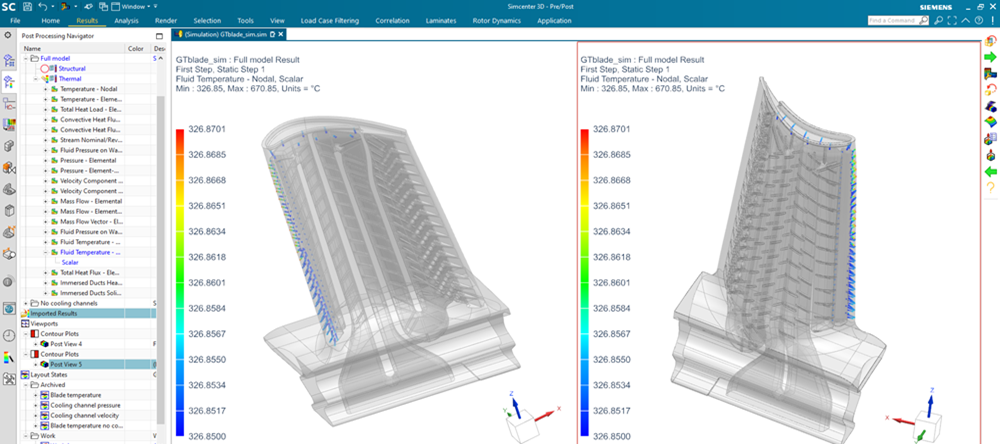
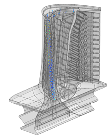
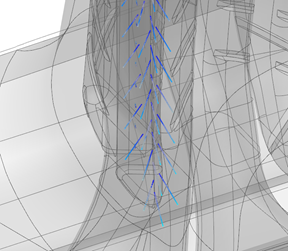
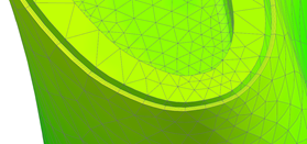
Our approach to solve this problem in Simcenter 3D Thermal Multiphysics is to approximate the holes with 1D immersed ducts. This allows the analyst to take into account the thermal effect of fluid flowing through the cooling channels without having to mesh them in 3D. Indeed, because of their (relative) small size, a 1D representation is sufficient to properly capture the heat transfer between the fluid and the solid. Furthermore, by “immersing” the duct, the analyst can mesh the 3D blade and the 1D duct network completely independently. The solver automatically performs the coupling.
Computed at solve time are the intersection between the duct and solid elements, the wetted area and the corresponding heat transfer between the fluid and solid.
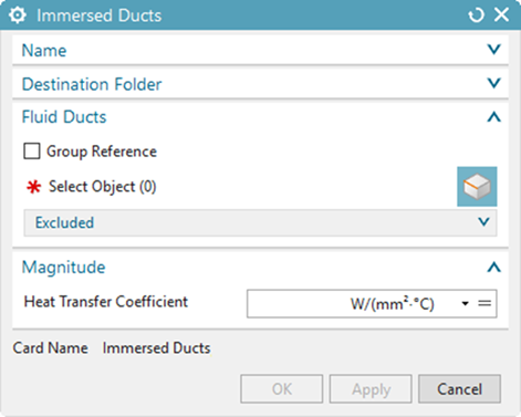
Using the Immersed Duct simulation object:
- The user selects the ducts and defines the Heat Transfer Coefficient (HTC)
- The HTC can depend on fields, expressions, or plugin function correlations
- The association to the underlying solid mesh is based on the radius of the duct element
The fact that the 1D network is completely independent from the solid mesh greatly reduces the modeling time, eliminates the tedious meshing process and reduces the mesh count. It also enables quick design variation that would be very difficult otherwise.
Immersed ducts are available for both thermal finite volume and finite element solvers. They have been validated against explicit modeling of the holes.
Thermal Protective Layers for Blade Cooling
Another approach often used in conjunction with the cooling channels to limit the temperature of the blades and improve the efficiency of gas turbines is the use of thermal protective layers. These layers, also called thermal barrier coatings, are very thin layers of advanced materials like zirconia sprayed onto the surface of the blades.
So why is modeling thermal coatings such a significant challenge? That is because each layer can be of a different material with a unique spatial thickness distribution.
In Simcenter 3D 2019.1, we introduced a new Thermal Protective Layer simulation object compatible with our thermal finite volume (FV) solver. It instructs the solver to automatically create multilayer shell elements with a new three-node formulation. Temperature results were then available on the different shell plies.
However, because of the high temperature difference between the hot gas and the metal substrate, very high thermal gradients can exist even within a particular layer. To properly capture these gradients, additional calculation points through the thickness are required.
A new approach compatible with our thermal finite element (FE) solver is available with Simcenter 3D 2021.2. With this new approach it is now possible to define the number of sublayers within any particular layer.
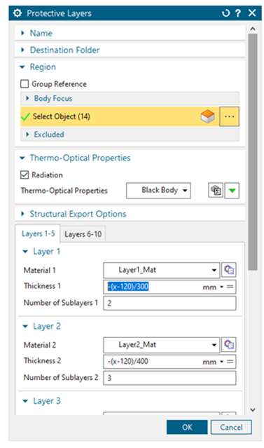
Each layer is defined by
- its material
- its thickness (itself defined by a constant, a field or an expression)
- the number of sublayers
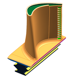
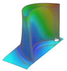
As with the immersed ducts feature, the FE solver creates a 3D mesh for each layer and its sublayer(s), greatly simplifying the modeling process. Once solved, it is easy to post-process each layer individually by selecting the automatically created groups in Simcenter 3D Post.
Boundary Condition Interdependency graphs
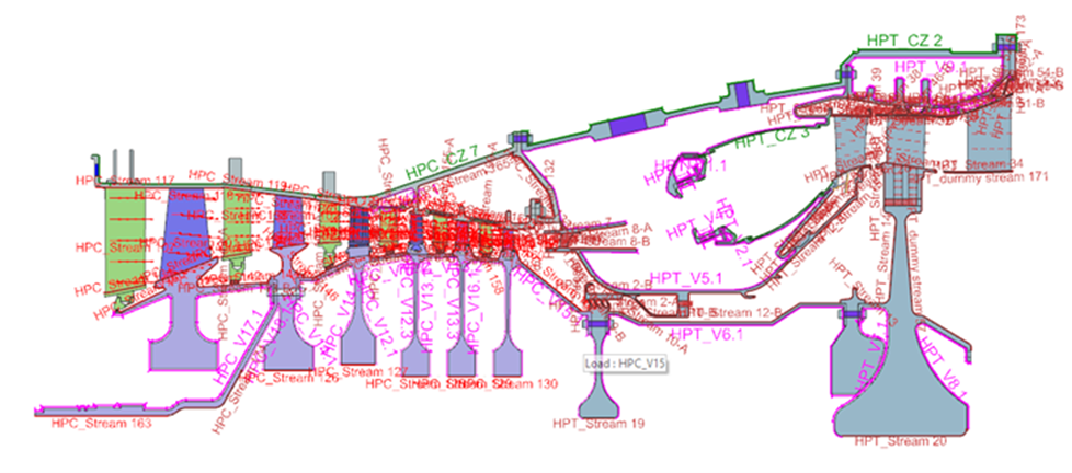
In a whole-engine thermomechanical analysis, fluid flow is often represented by specialized turbomachinery thermal convective boundary conditions (i.e., thermal streams, convective zones, and voids). The complex way these boundary conditions are interconnected makes diagnosing and tracking down model setup errors difficult. For instance, the outlet of one stream can feed one or multiple streams, or a stream can feed a void. See the figure below for an example.
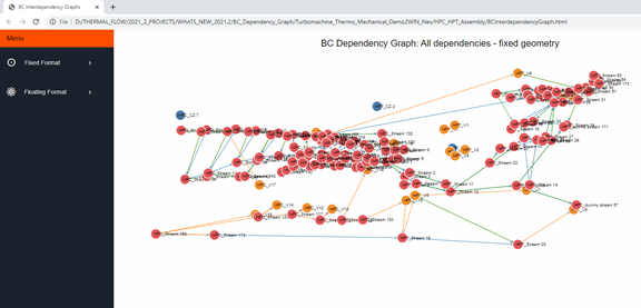
To help verify thermal convective boundary conditions are correctly setup, the new BC Interdependency Graph provides a visual tool.
The thermal solver produces an HTML report to view the interdependencies in a dynamic manner. The “Fixed Format” view displays the boundary conditions as they would appear spatially in the model, while the “Floating Format” view displays the boundary conditions with an emphasis on the connections between them. It is possible to zoom and pan the display to focus on specific parts of the model or to focus on either temperature or mass flow dependencies. It is also possible to move the nodes around for better viewing.
In summary
These are just a few of the many enhancements and new features that will be available in the coming Simcenter 3D 2021.2 release. Immersed duct modeling of cooling channels significantly reduces the model setup and run time for blade cooling analysis. The FE solver can automatically model and compute thermal protective layers, which makes post-processing easy once the calculations are done. Finally, the new BC Interdependency Graph helps to quickly and easily verify that very complex boundary conditions are setup correctly.
For more information on simulation modeling in Simcenter 3D