Dynamic sloshing with hydro-elastic modes: Do you know how to follow the only existing CAD & CAE workflow?

Sloshing
When a structure such as a tank, container, or vehicle carries a liquid with a free surface, the surface vibrates due to gravity waves. The liquid will move back and forth violently due to resonance which occurs when the slosh frequencies are excited due to external loads or motion. This will, in turn, impact the performance and integrity of the container. The goal for a Design Engineer is to design the equipment such that the slosh and hydro-elastic resonance modes are avoided.
The Sloshing phenomenon is nothing new, and we probably encounter this daily. A coffee mug containing coffee that is not full to the brim can experience large oscillations even for small motions, for example, when walking or driving a car at a steady speed or even riding a train. Studies have shown that we consciously or subconsciously adjust our movement or grip to avoid spills by moving the excitation frequencies lower or higher than the resonant frequencies.
While the above example was merely an illustration of sloshing, more practical and relevant examples include sloshing of (a) fuel in aircraft and rocket fuel tanks; (b) cargo, ballast, or fuel tank of large ships; (c) fuel tank of an automobile, and (d) rail and road transportation of liquid fuels.
Sloshing in Space
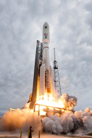
Let us consider the case of liquid propellants in launch vehicles. Liquid fuel forms a large percentage of the initial weight of the launch vehicle. In this case, the dynamic forces due to fluid motion can be substantial. To counteract such forces, launch vehicles are equipped with control systems – also known as guidance control systems. With sloshing, there are three sets of resonant frequencies (or modes) of interest: (i) slosh frequencies due to gravity waves, (ii) resonances of the container (also known as hydro-elastic modes), and the (iii) resonance of the control system. If the dominant fuel-slosh frequencies coincide with the control system frequencies, they excite the slosh modes and set the liquid into violent motion. This motion is particularly undesirable as it adversely affects navigation. If the control system frequencies instead coincide with the natural or resonant frequencies of the container, the container is set into severe vibration leading to its catastrophic failure. Determining resonant frequencies of the sloshing and hydro-elastic modes is vital for launch vehicle design.
Sloshing on the road

According to Mckinsey reports, natural gas will be the strongest-growing fossil fuel between 2020 – 2035 and decline slightly after that from 2035 – 2050. It is usually transported from refineries to shipping terminals and from shipping containers to LNG (liquified natural gas) depots. For transportation, the natural gas is converted to its liquified form (liquid natural gas or LNG) by cooling the natural gas to very low temperatures. Vehicle motion at certain speeds can excite slosh modes, resulting in violent liquid motion and hence swaying of the vehicles on the road.
Determining Resonant Frequencies
The two use cases of launch vehicles and natural gas transportation emphasize the importance of quantitatively determining the resonant frequencies of the slosh and the hydro-elastic modes. Since the excitation is often difficult to control, the design Engineer can design the liquid-filled containers such that the slosh frequencies and the container hydro-elastic modes are farther away from the excitation frequencies. Needless to say, that design will require multiple configurations and what-if studies.
Two main approaches have been available for modal analysis up until recently: (a) laboratory testing on scaled models and (b) simulation using Computational Fluid Dynamics (CFD) approach.
It is no secret that what-if studies with the test-based approach can be expensive, very time-consuming, and labor-intensive. On the other hand, a detailed CFD approach requires the knowledge of the load history or excitation time history, and there is no direct way to predict resonances using a CFD approach. Again, as in the test-based approach, this method is also time-consuming.
There has been plenty of research to simplify the mathematical models leading to linear dynamic analysis. However, this analysis also has challenges; hence, no commercial finite element code has been available to perform slosh analysis.
Let’s examine the complexity of computing the resonant modes with linear dynamic analysis. For simplicity, let’s assume initially that the free surface doesn’t slosh. Finite Element Analysis (FEA) will result in a stiffness matrix that is sparse but will also result in a mass matrix that is dense. The mass matrix becomes dense due to the added fluid mass (added at the wetted boundary). A dense mass matrix requires large storage (memory/disk). It also makes it difficult to extract normal modes using traditional methods. Practical models with complex geometries then require efficient algorithms to compute the resonant frequencies.
Additional computational complexities are introduced if we now add the free surface to slosh to the mix. Sloshing gravity waves result in many modes. There are as many slosh modes as the number of nodes on the slosh surface. For example, if there are 500 nodes on the surface, there will be 500 slosh modes. Applications such as launch vehicles and transportation of liquid fuel involve very large tanks, and having 500 to 1000 nodes on the slosh surface is not unexpected. To compute the first structural mode (also known as hydro-elastic mode), we need even more modes to be computed. In the above example, more than 500 modes need to be computed. The computational cost of extraction of more modes reasonably fast becomes a challenge.
Simcenter Nastran and Simcenter 3D
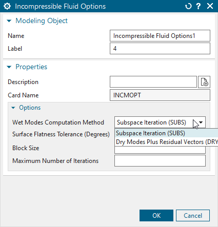
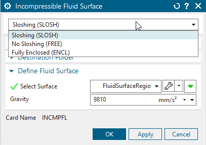
Slosh modeling in Simcenter Nastran addresses the challenges mentioned in the previous paragraph relating to the efficient computation of normal modes (resonant frequencies). Simcenter Nastran offers two methods to efficiently compute the resonant frequencies: (a) an iterative approach, like the popularly known “subspace iteration” technique, and (b) “dry modes” which uses the dry modes as the initial guess vector to compute the slosh modes and hydro-elastic modes.
Another very important aspect is that Simcenter Nastran allows the structure and fluid domains to be modeled using different mesh densities. That is, it obviates the need for coincident nodes at the fluid-structure interface (wetted boundary). This allows the structure and the fluid domains to be meshed independently.
Simcenter 3D is an authoring tool that offers various ways to create the CAD model of the structural domain. It also has tools to create the fluid domain, given the structural domain. For example, using synchronous modeling technology, fluid geometry can be easily created from structural geometries. For complex geometries, “Surface Wrap” functionality can be used to create the fluid domain. The main benefit of using Simcenter 3D is its tight CAD integration. Design changes to perform what-if studies can be made to the CAD, and the node and elements automatically regenerated. If the constraints are applied on the geometry, these are automatically regenerated as well. Let us now look at some concrete examples.
Results
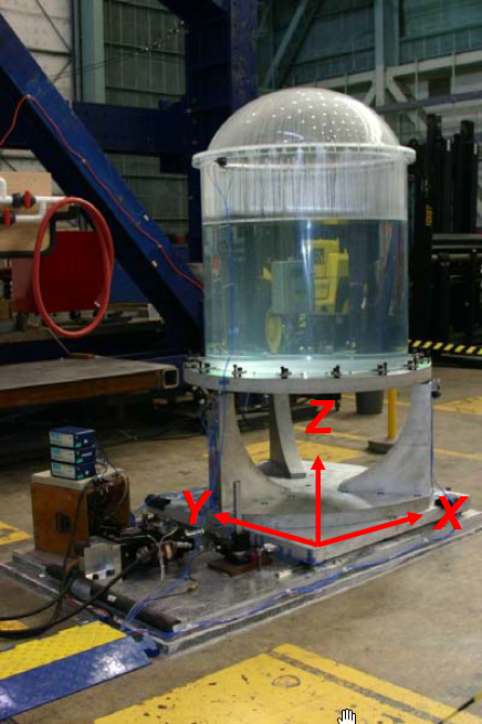
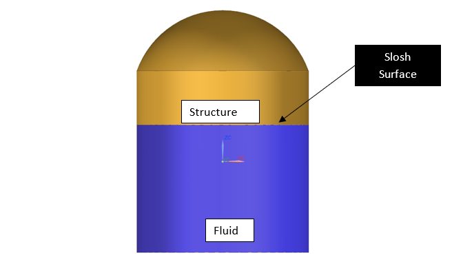
The figure below shows a container filled with water. It was modeled to resemble, topologically, a launch vehicle’s liquid hydrogen tank (LH2). The mesh density was such that the total number of degrees of freedom for this moderately sized model was about 403,000, with approximately 204 nodes on the slosh surface.
Linear dynamic analyses result in 204 slosh modes – identical to the number of nodes on the surface of the fluid domain. The total elapsed time to compute the first 30 modes is about 60 seconds, and the first 300 modes (204 slosh modes + 96 hydro-elastic modes) was around 15 minutes. These run times are small enough to perform a plethora of what-if studies.
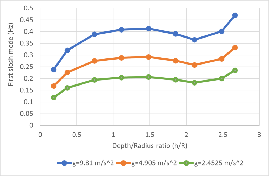
Gravity is known to play an important role in determining sloshing characteristics. Figure 5 shows how the first slosh mode changes with the depth of the liquid in the container as a function of gravity. Resonant frequencies shift to lower values when gravity is lowered, for example, in space conditions.
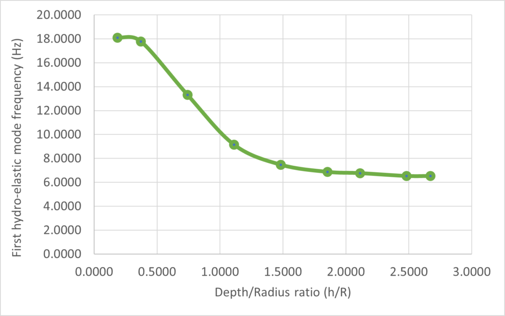
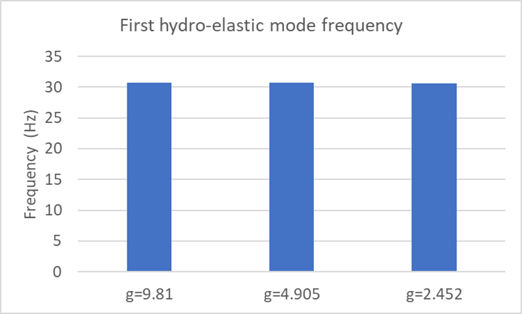
Figure 6 depicts the first tank (hydro-elastic) mode as a function of the height of the liquid column. As the height of the liquid column increases, the resonance frequency decreases, but beyond a certain height, the hydro-elastic mode seems to be independent of the height of the fluid column. An effect that does not seem to be affected by gravity as seen in Figure 7 that shows the hydro-elastic modes seems to be independent of the gravity value.
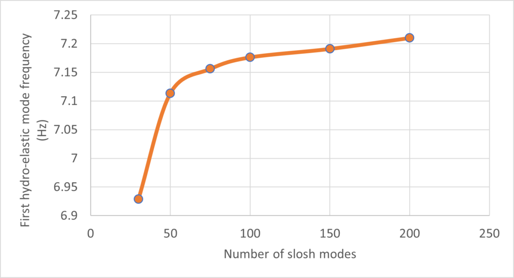
As indicated before, the number of slosh modes is primarily governed by the number of nodes on the slosh surface. That is, the finer the fluid mesh, the greater the number of slosh modes. To compute the hydro-elastic mode, it often becomes mandatory to compute at least as many modes as the number of surface nodes on the slosh surface. This can quickly become very expensive if there are many surface nodes. The computation cost of more modes can be exponential. Often, only the first few slosh modes are important. Retaining just a few of the important slosh modes can therefore cut the cost of computation quite drastically. Simcenter Nastran can use a component mode reduction technique to retain just the first few slosh modes. The following figure shows that retaining just the first 50 – 100 slosh modes can give a good convergent result compared to having to compute 400 to 500 slosh modes.
Summary
Sloshing is very important in many applications. There are two important aspects of sloshing: (a) predicting its onset, and (b) mitigating the effects of sloshing once sloshing starts. This article is primarily focused on predicting the onset of sloshing using modal analysis.
Avoidance of the resonance that induces slosh will also reduce the pressure of the liquid on the walls of the container. However, a side effect may be that the container itself is set to a resonance that can cause catastrophic failure. Therefore, to prevent sloshing and reduce the risk of container failure, it is better to consider the coupled effects of liquid and the container and then determine the coupled hydro-elastic modes. This technique ensures that the modes that initiate both sloshing and failure do not occur. Until now there has been no commercially available package that can predict the slosh and hydro-elastic modes in a very efficient way for practical problems. This is all the more important for large problems that result in a large number of slosh modes.
With the new release of Simcenter 3D and Simcenter Nastran Engineers can easily set up slosh analysis in Simcenter 3D desktop application. The tight integration of CAD and CAE in Simcenter 3D is particularly helpful in performing what-if analysis with a varying fluid volume inside the container. Together with Simcenter Nastran as the solver, slosh analysis of even large-size models can be computed very efficiently. In addition, using the component mode synthesis method, the user can focus on just the important slosh modes while computing the hydro-elastic (coupled fluid-structure modes). This makes high-fidelity simulation a reality.
Simcenter 3D 2212
The features discussed in this blog were first introduced in Simcenter 3D 2212, to find out what other updates are featured in this release see this blog.