Internal Combustion Engine CFD with Simcenter STAR-CCM+ In-Cylinder Solution

_________________________
Simcenter STAR-CCM+ In-Cylinder Solution, an add-on to Simcenter STAR-CCM+, offers an in-cylinder-specific workflow, which involves minimal inputs, streamlined pre-processing and automated post-processing capabilities, all built around a fully automated grid generation, which relies on a morph-map approach. Complemented by class-leading models (spray, liquid film, ignition, combustion, emissions) and embedded design exploration capabilities, it helps you realize ICE CFD simulations in a productive way, enabling you to numerically predict the next, more efficient and more powerful engine design.
ICE Workshops – Now available for Replay
Take the occasion and learn more about the Simcenter STAR-CCM+ In-Cylinder Solution by watching the recordings of our ONLINE events:
2025 | 2024 | 2023 | 2022 | 2021
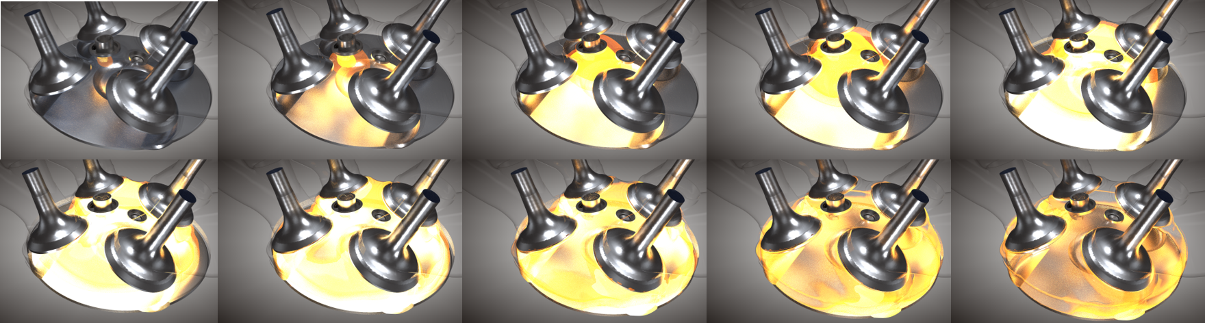
In one of the most interesting examples shown in 2023 webinar, illustrated below, ammonia and diesel jets at various injection timings and angles have been studied and, for certain conditions, insufficient or too strong interaction of the two fuel sprays, for instance misfiring, can occur. Being able to rely on CFD for an accurate prediction of the phenomenon, reduces the need for extensive testing and allows for detailed understanding on how to design an engine, in which the scenario can be avoided.
Simcenter STAR-CCM+ In-Cylinder Solution
While we all continuously hear about the electrification of automotive powertrains, the reality is that the internal combustion engine will not disappear anytime soon and will be a staple of powertrains for decades to come. The push to downsize the internal combustion engine and the integration into hybrid powertrain platforms present many new challenges for engine development which can only be overcome using extensive CFD simulation.
The In-Cylinder Solution, add-on to Simcenter STAR-CCM+ allows you to perform accurate in-cylinder CFD simulations of engines easily. Default settings and automatically-created post-processing output aim at giving the engineer a “running start”: you don’t need to be a CFD expert to set up and carry out one of the most challenging CFD simulations around!
Simcenter STAR-CCM+ In-Cylinder Solution benefits and features at a glance:
- Simple Problem Set Up: setup an engine simulation in minutes
- Automated Meshing: morph & map takes care of moving components
- Cold Flow: maximize trapped air mass
- Charge Motion: improve mixing of inducted air and injected fuel
- Combustion, Knock & Emissions: maximize combustion efficiency, minimize harmful emissions
- Conjugate Heat Transfer: optimize thermal management with coupled powertrain analysis
- Workflow / Post-processing: boost productivity with minimal inputs and streamlined processes
- Automated Design Exploration: automatically optimize engine performance
- Validation: excellent correlation with experimental data
Return to top. ^
Simple Problem Set Up
The In-Cylinder Solution add-on opens up a minimal interface which shows only those inputs required for setting up an in-cylinder simulation, presenting a top-down workflow: you start at the top and work your way down through various levels.
You do not have to be an expert Simcenter STAR-CCM+ user to set up and run in-cylinder simulations using the add-on, as it uses an application-specific workflow and simplified interface. However, expert users can use those in-cylinder simulations as the starting point for performing more complicated multi-physics engine simulations that exploit the full range of Simcenter STAR-CCM+ simulation capabilities.
The Simcenter STAR-CCM+ In-Cylinder Solution has been specifically developed to make setup quick & easy and leave time for the analyst to spend on engineering the solution rather than setting up the problem with lots of mouse miles and button clicks. From fast setup of typical multi-hole injectors which can easily be customized for spray targeting, to quick selection of fuels, to automatic setup of common post-processing outputs like liquid and vapour penetration plots and fuel mass tracking, the add-on has been designed and developed to make the simulation setup easy and allow engineers to derive the most value out of the simulation process.
You are now being offered the tool and capabilities to setup a full-, half- or sector model, to simulate both a four- and two-stroke engine configurations, all within only a couple of minutes.
Automated Meshing
The In-Cylinder Solution add-on employs a simulation driver to run a transient mesh motion process. You only need to create a single initial mesh, comprised of trimmed cells and prism layers to capture boundary layer flow features. The entire mesh movement is automatically taken care of by the code, which automatically morphs & maps the grid to account for the motion of the piston and valves. The tool performs quality checks on the mesh as it morphs, automatically creating a new, undistorted, mesh when necessary and mapping the simulation results onto it.
The mesh is automatically refined in critical areas in line with best-practices: around the valve, the valve seat, the valve throat, up into the ports and around the gasket gap. This is performed automatically for every simulation and does not require any manual intervention by the user. On the other hand, users have complete control over the mesh setup and can add additional regions of refinement, e.g. around a spark plug, as dictated by the scope of their analyses. In case the latter refinements are not needed throughout the engine cycle, a dedicated UI panel caters for a practical on/off-type switch of a temporally varying grid refinement – only in version 2410 or newer!
The employed morph-map approach has been extensively tested and is highly conservative of mass for all practical applications.
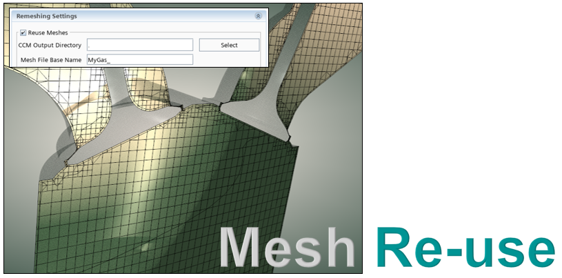
You can also reuse generated & stored meshes. This effectively eliminates grid generation time in the second engine cycle onwards, particularly useful in LES studies were many cycles have to be simulated to accurately capture cycle to cycle variability. Each mesh station in the cycle is saved as a file with .CCM extension in a pre-specified output directory and the °CA in the filename acts as the mesh identifier.
This approach is particularly beneficial in LES studies, where a higher number of engine cycles need to be simulated in order to accurately capture cycle-to-cycle variability.
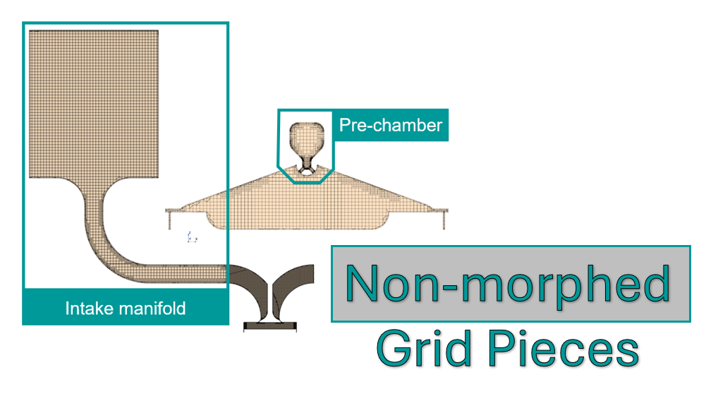
Since version 2406, you can also include geometry parts meshed in a static way, thereby saving the time the morpher would spend to morph and map the grid. Be it intake plenum, body of a pre-chamber or else, this functionality comes handy whenever cell vertex movement is not important. The grid can be coarser in those areas, something that previously posed a few challenges. Note you can now benefit from a streamlined specification of initial & boundary conditions, for those parts, which enables you to arrive at the same setup that would normally require up to 3x more clicks, i.e. to manually include static-meshed parts.
Return to top. ^
Cold Flow
An in-cylinder simulation is amongst the most complex CFD simulations you can perform. The combination of high-speed flows, mesh motion requiring an extremely high level of mass conservation, and very small time scales (fractions of a crank-angle degree typically need time steps in the order of 1E-6 [s]) means a lot of work goes into the setup, and the numerics must be carefully selected to accomplish stable runs with reasonable turn-around times. This is even before we start layering on complex physics models upon including liquid fuel injection, e.g. Lagrangian spray, droplet-wall interaction, wall fluid film, and combustion, e.g. ignition, flame propagation, emissions formation, knock.
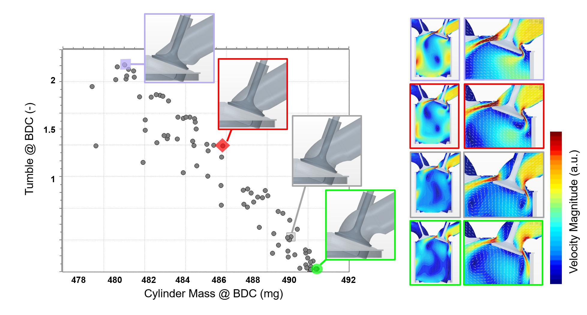
For this reason, a lot of simulation performed early in the development process is concentrated on so-called cold-flow. This involves modeling the transient process of the airflow in the cylinder, typically with the objective of maximizing the trapped air mass and examining the bulk motion – swirl and tumble – that this flow induces. Often we also look at the evolution of turbulence to better understand the potential for fuel and air mixing and, specifically in spark-ignited engines, what the turbulence levels around the spark plug are at the intended time of ignition / start of combustion.
Simcenter STAR-CCM+ In-Cylinder Solution allows you to set up cold flow simulations for multi-valve engines with the automated setup of mesh motion, letting you go from raw CAD geometry to running simulation in just minutes.
Either URANS or LES can be employed, depending on the exact scope of your simulation projects and the effects to be captured numerically.
Return to top. ^
Charge Motion / Mixture Preparation
Expanding the list of available functionalities, we had taken a big step forward with capabilities to set up and run charge motion simulations. This built upon our previous cold flow capabilities by including the setup of liquid fuel injection and modeling the ensuing mixing process. Charge motion simulations allow engine manufacturers to improve combustion quality, by controlling the mixing of inducted air with injected fuel by identifying and rectifying rich or lean mixture regions, especially in critical parts of the cycle, such as when the piston approaches TDC and during spark ignition. The latter is especially important in today’s direct injection designs, in which the injection of fuel directly into the cylinder greatly impacts the bulk flow and turbulence level – the insight provided by simulation is more important than ever.
Another critical role, a charge motion simulation usually plays, is the assessment for potential formation of harmful emissions. Again, ideally, we want to achieve high-quality mixing of fuel and air, especially challenging in direct injection systems, in which, at high load operating points, there is fuel injection during large portions of the engine cycle. Simulation tells us not only where we have lean and rich pockets of charge, but how fast the liquid fuel is evaporating, how much is impacting on surfaces in the cylinder, and whether it’s forming films or pools on those surfaces. All of these act as indications of the magnitude of harmful emission formation which, unless somehow mitigated, will need to be “cleaned up” downstream of the engine using expensive aftertreatment devices in the exhaust line.
Over the years OEMs have developed large databases for design guidelines based purely upon charge motion, using just the bulk motion inside the cylinder, metrics of fuel and air mixing quality, and levels of turbulence around the spark plug which tell them whether combustion is going to be good or not, saving them valuable engineering time, especially in the early design stages of a combustion system.
A wide variety of break-up, droplet-wall impingement, as well as liquid film models provide the needed toolset for users to be successful in this kind of simulations, prior to carrying out more advanced, combustion, studies. Moreover, temperature-dependent properties applied by default in versions 2210 or newer, significantly reduces manual interaction:
As far as high fidelity in simulating fuel sprays is concerned, adopting constant properties is far from sufficient. The burden on the user, however, to manually switch properties of the Lagrangian phase to temperature-dependent values, is quite high. Using Simcenter STAR-CCM+ In-Cylinder Solution, this step is fully automated by making use of data stored in a database, being shipped with the software.
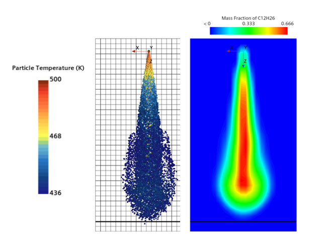
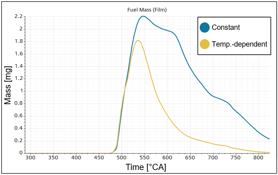
The benefit becomes more apparent in plots like the one on the left. Capturing mixture preparation accurately is of utmost importance in order to have the correct mixing of fuel & air before proceeding to the stages of in-cylinder combustion. Fuel mass is depicted here with constant versus temperature dependent properties.
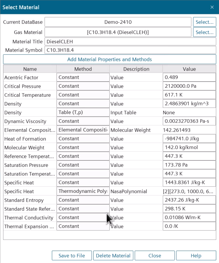
In version 2410 onwards, a streamlined workflow, to fully customize fuel materials & libraries is also being offered, encompassing UI panels to facilitate specification of substance properties.
Return to top. ^
Combustion, Knock & Emissions
Simcenter STAR-CCM+ In-Cylinder Solution offers combustion capabilities, e.g. ECFM-3Z and ECFM-CLEH, an advanced (ISSIM) as well as a standard ignition model, knock models (Tabulated Kinetic Ignition – TKI), complemented by emission models, such as CO, NORA NOx and soot emission models, for example Soot Sectional Method. With three releases per year, we are continuously increasing the breadth of capabilities with further high class combustion model options and sub-models to capture knock & predict emissions.
The increasing interest in modeling of alternative / non-carbon fuels being the driving factor, all combustion models offered in the code, are fully compatible with any fuel of type CxHyOzNw, such as hydrogen (H2) and ammonia (NH3).
At more extreme operating points and pressure / temperature conditions, certain assumptions that were valid previously, such as the ideal gas law, may not hold any longer. To stay on the safe side, real gas using the Redlich-Kwong model, offered in the tool, helps users to accurately predict effects the ideal gas law can’t, such as Van der Waals forces, compressibility & non-equilibrium thermodynamic effects, variable specific heat capacity etc.
To generate useful combustion chamber design information without relying on a detailed model, the Specified Burn Rate (Wiebe) model can be employed, specifying the burn rate via a form factor together with the duration of combustion. The approach can be, as well, used to generate heat transfer boundary conditions for use in an engine CHT analysis.
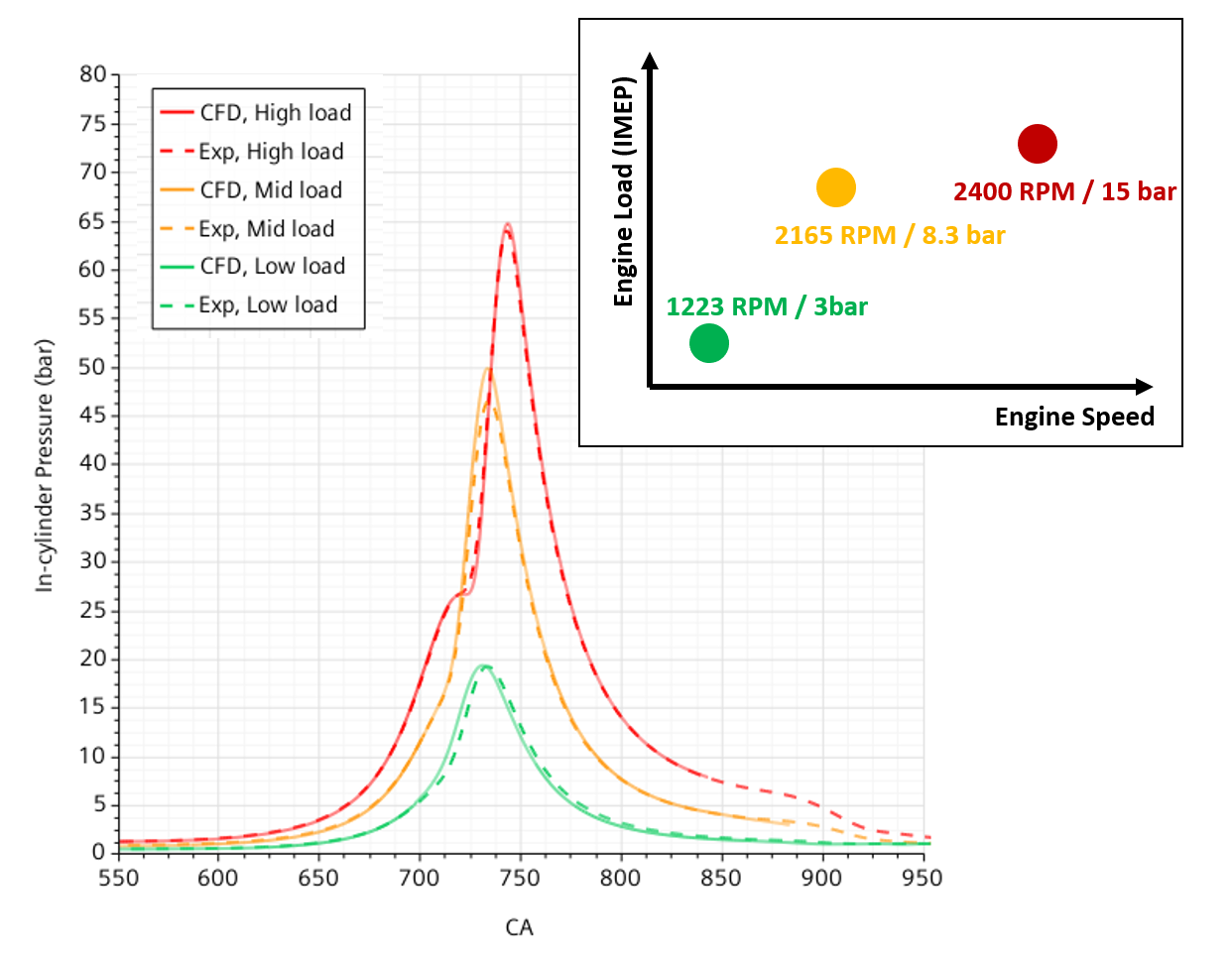
The graph shows a cylinder pressure curve from an industrial 4-stroke diesel engine. Here the application of the real gas model improves the prediction of the cylinder pressure for both a part and full load operation condition, with the peak pressure more closely matched to test data.
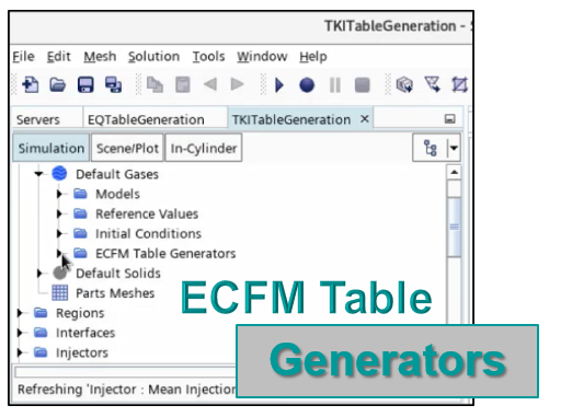
Modelling combustion & emissions in some cases requires libraries of pre-tabulated chemistry. Instead of generating those using either DARS or third-party tools – or making use of tables for standard fuels available on Support Center – you can now take advantage of the ECFM table generators: the functionality allowing to generate tables for (i) laminar flame speed, (ii) engine knock, (iii) soot, (iv) equilibrium, the latter needed in simulations with ECFM-CLEH combustion model. Note that in Simcenter STAR-CCM+ 2502 we also achieved a speed-up up to a factor of 1.5x in laminar flame speed calculations thanks to an improved parallel distribution method.
This provides additional flexibility by removing reliance on external tools.
Find out more about the Combustion Capabilities
Watch our On-Demand Webinar on CFD simulation of in-cylinder combustion
Conjugate Heat Transfer (CHT)
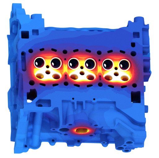
Going beyond standard simulations, with downsizing for efficiency in today’s engine designs, effective thermal management is critical. Designs reaching peak levels of thermal efficiency without exceeding thermal design limits are studied using full-engine conjugate heat transfer simulations.
Simcenter STAR-CCM+ In-Cylinder Solution also provides a single user environment to simulate both the fluid and the solid side, i.e. the in-cylinder & engine CHT models. The exchange of heat transfer boundary conditions between the two models, as well as the ability to automate the workflow, are points that can be realized in a straight-forward manner:
Users are offered an automated way of calculating and exporting cycle- averaged boundary heat transfer data (averaged spatial heat transfer coefficients and reference temperatures), which will, in turn, enable thermal boundary conditions to be applied in a subsequent engine CHT analysis. The workflow therefore becomes significantly more streamlined and efficient.
Traditionally, the in-cylinder / CHT approach required usage of multiple CFD packages. Different file formats required and data mapping between software packages have always posed operational challenges. Now that the coupled in-cylinder/engine CHT analysis can be carried out entirely within Simcenter STAR-CCM+, the overall process is greatly simplified and allows for automation of the combined simulation cycle through JAVA scripting.
Return to top. ^
Workflow / Post-Processing
The application-specific workflow of Simcenter STAR-CCM+ In-Cylinder Solution requires minimal inputs by the user, thereby decreasing the overall turnaround times. Several functionalities enable a seamless pre- and post-processing of in-cylinder simulations. Only a small subset of those is depicted here.
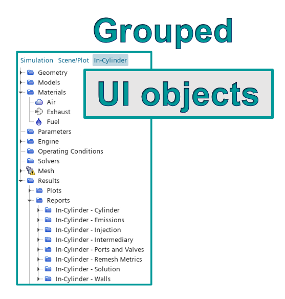
The add-on presents users a grouped list of UI objects decreasing “mouse scrolling miles” to find the object of interest. Usage of subfolders enables categorization based upon the domain part (cylinder, ports/valves) or nature (mesh, solution, physics). The benefit of this will be even more apparent in multi-cylinder cases, planned to be incorporated into future versions.
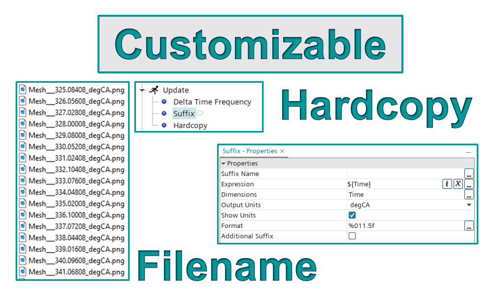
Generating / exporting plot & scene hardcopies, the capability allowing users to fully customize the filename, results in a file list already in chronological order, with °CA / degCA as a direct indicator. Hence, the list can also be used for video generation without manual conversion of image filenames.
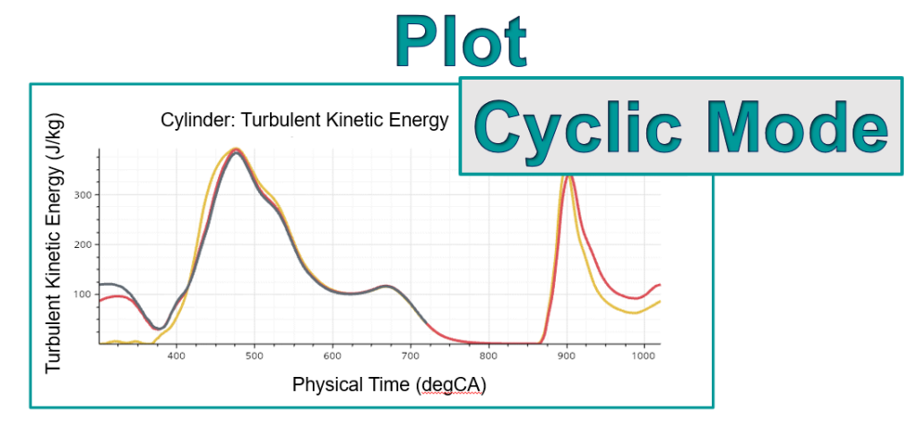
Another useful functionality, Cyclic Mode of plots, allows visualizing data in a cyclic pattern, particularly useful in in-cylinder analyses. Leveraging the feature allows users of the add-on to compare engine cycles by plotting the corresponding 2D (X-Y) curves on top of each other, highlighting differences out of the box; that is without any form of manual interaction, since the mode is by default active in all relevant plots.
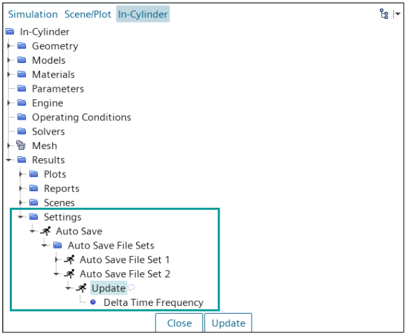
In versions 2410 or newer, a much more versatile Auto Save functionality, with introduction of the File Sets concept, eliminates reliance on both JAVA macros and Simulation Operations – required previously – in scenarios that necessitate I/O output at different save-to-folder frequencies.
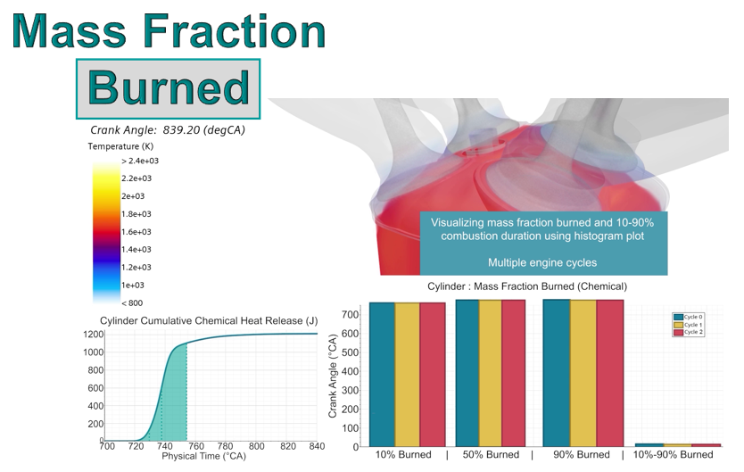
Finally, with another useful and recently introduced post-processing feature, visualizing integrated heat release rates, mass fraction burned (MFB) 10-50 or 90%, as well as the combustion duration, is zero clicks away, thereby taking productivity to the next level. Stop exporting heat release curves and carrying out tedious computations manually, in spreadsheets, in order to assess the performance of your engine design. All tree objects needed to evaluate those quantities are generated automatically.
Click here to interactively explore more results in an ammonia-fueled engine!
Automated Design Exploration
Unleashing the power of the Simcenter STAR-CCM+ as a platform, with the embedded tool Design Manager, users can leverage the automation capabilities, scalability, and flexibility of the platform to easily and quickly execute design studies in order to optimize their engines for the next generation.
Additionally, since the In-Cylinder Solution add-on automatically creates a parametric model, you are only a few mouse clicks away from easily sweeping multiple operating conditions to understand the bulk motion and turbulence at different speeds & loads.
A swap of geometries has also been introduced allowing for easy setup of geometric design variation studies and the re-use of existing simulation setup on another geometry.
Return to top. ^
Validation against experiments
Both the In-Cylinder Solution and Simcenter STAR-CCM+ have been extensively validated for engine simulations, using both proprietary and public domain engine designs. One example is our validation of the University of Michigan Transparent Combustion Chamber-III (TCC-III) Optical Internal Combustion Engine, which is a 2-valve head, 4-stroke, spark-ignition engine with a pancake-shaped combustion chamber.
The results demonstrate excellent correlation with global thermodynamics variables, including cylinder trapped mass, pressure, and temperature, and, compared with visualization from the experimental rig, the major features of the flow field are also well captured.
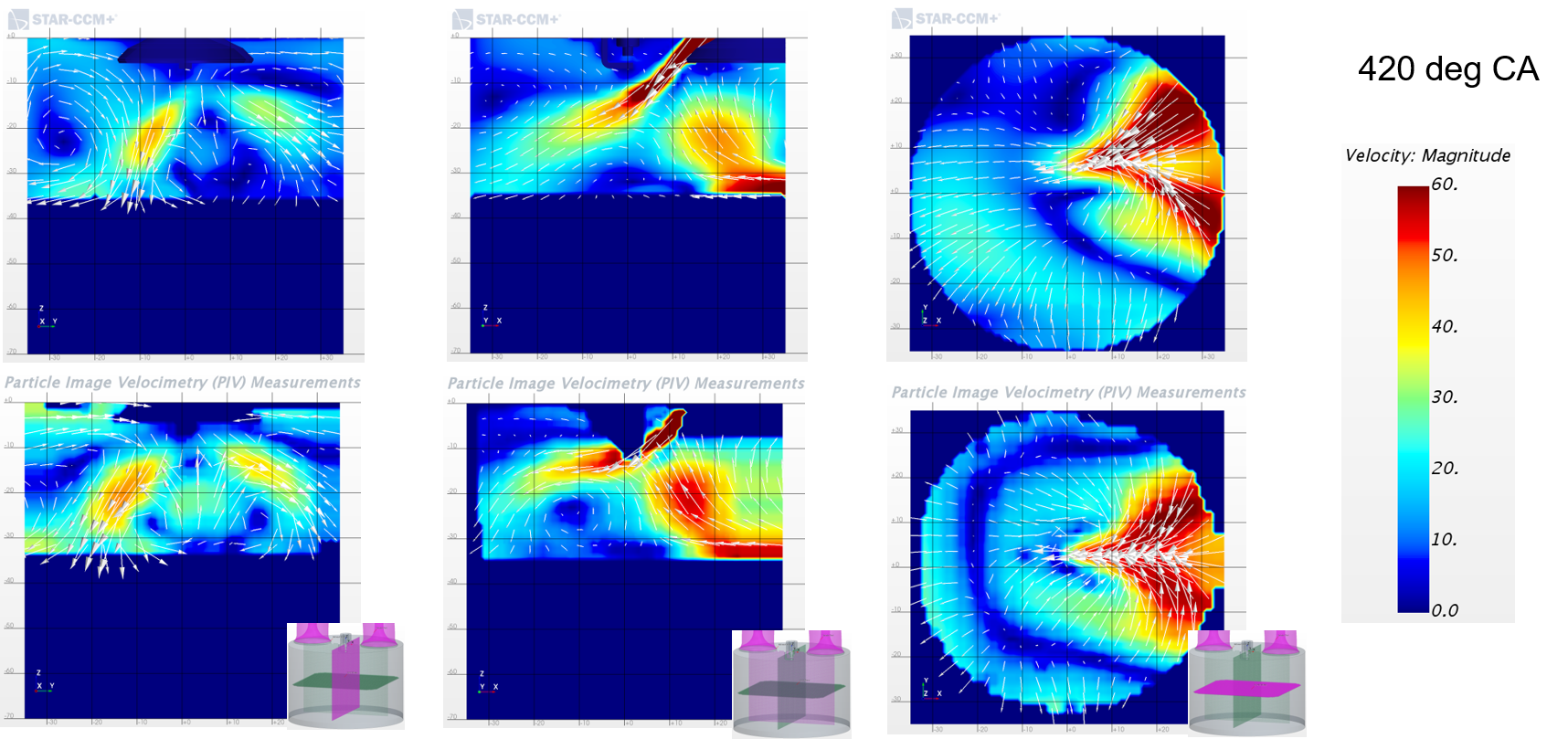
Another detailed validation study has been conducted with the Research and development department of Daimler AG, proving excellent correlation between high-speed / high resolution PIV measurements and Simcenter STAR-CCM+ predictions in a state-of-the-art GDI engine configuration.
For more details on our combustion validation watch the On-Demand Webinar on CFD simulation of in-cylinder combustion held virtually in 2019.
Return to top. ^
Committed to the IC Engine Market
Siemens Digital Industries Software is completely dedicated to the IC engine simulation market, recognizing that internal combustion engines are here to stay and that only advanced simulation can deliver the cleaner more efficient engines that society deserves.
As part of Simcenter STAR-CCM+, the In-Cylinder Solution add-on receives updates three times per year and we will continue to add features that address these simulations.
At any time, a dedicated team of outstanding engine CFD experts will be there to support you, solving even the toughest problems in in-cylinder CFD.
Return to top. ^
For information on the Siemens CFD offering for ICE applications, to download Simcenter STAR-CCM+, or to spawn a support query, please visit Support Center.
To ask your questions and engage with the community, please visit the In-Cylinder Flow & Combustion community page.


Comments