Rotor blade aeroelasticity to the rescue!
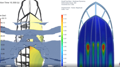
Applications such as helicopters, urban air mobility vehicles and wind turbines heavily rely on accurate predictions of the complex interaction between aerodynamics forces and structural responses of their rotor blades. Hence, to increase the performance of those rotors while reducing vibration and noise, high-fidelity aeroelastic simulations are a key enabler for CFD engineers. Simcenter STAR-CCM+ 2206 offers a fully automated rotor blade aeroelasticity workflow that provides a high-fidelity solution (rotor blade CFD/CSD coupling).
Houston, Texas in 2017.
Powerlines down, debris-strewn flood waters still coursing, thousands of people trapped on top of their houses, cars, garages – or what’s left of those. Hurricane Harvey just hit the shores of the southern United States. Navy Seahawk Pilot Lt. Benjamin gets on a Seahawk to one of the many rescue missions which he would later describe as a “very task-saturated environment”.
Without doubt, the pilot knows this is a massive understatement considering the complexities involved in the rescue operations ahead. Such rescue operations are suited for only one sort of aircraft, where the difference is between life and death. Helicopters.
If a man needs rescue, an airplane can come in and throw flowers on him and that’s just about all. But a direct lift aircraft could come in and save his life.
– Igor Sikorsky
No one could have put it better than Igor Sikorsky a pioneer in Vertical Take-Off and Landing technology (VTOL). VTOL aircraft or rotorcraft are particularly suited for emergency medical, search and rescue operations and are expected to operate reliably under adverse weather conditions and extreme rescuing scenarios. During hurricane Harvey alone, helicopter rescue teams performed over 200 missions reaching people in dire need and evacuating them away from danger. Hundreds of lives saved of people bracing themselves on rooftops, stuck in their cars, or floating in the middle of the flood.
Engineered with a purpose
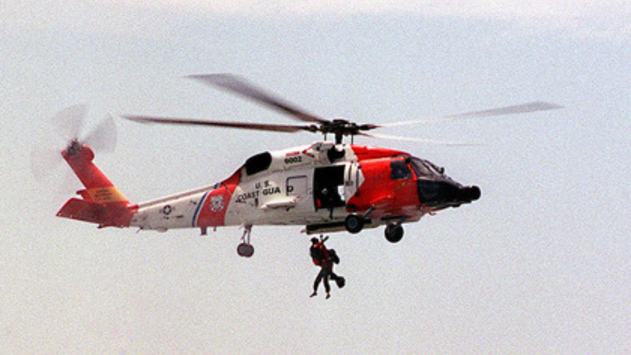
Each rescue mission called on the skills and training of the crew and the reliable operation of the helicopters to save lives. While the pilots could land the helicopters in some situations, in many others they hoisted people or rescue divers descended from the hovering aircraft to bring people to safety.
But saving those lives does not “just” rely on excellently trained teams and pilots. Setting aside the complexities involved in operating an aircraft in extreme operating conditions for a moment – such extreme conditions demand an extreme machine. A machine that requires highly sophisticated flying technology made possible by another type of hero. You will not see such heroes on the news, rather they can be found at their desk, crunching the numbers. This hero’s mission is to make better, more reliable, safer, stronger, more efficient, and faster helicopters. Rotorcraft aero/structural and design engineers.
Model the complexity to gain insights
But why is it so difficult to engineer a helicopter? And what role does Computational Fluid Dynamics (CFD) play in that?
Let’s start by considering the complexities on full display with rotorcraft. These marvels of engineering balance many competing requirements – high performance with quiet operation, light and flexible structures that are strong and robust, stable yet maneuverable flight, and so on. As engineers, we have an appreciation that while some systems are elegantly simple – an engineer’s job is seldom simple. To be successful we engineers need to model the complexity to gain the insights necessary to make good designs.
Accurate estimation of dynamic loads from the rotor blades is important for performance estimation of the aircraft throughout the flight envelope, as well as for sizing of the rotor components for safe operation. The rotor loads are also transmitted throughout the aircraft contributing to the vibratory loads.
Due to the complex nature of the aerodynamic environment in which a helicopter operates and the flexible nature of the blades, the problem is inherently aeroelastic. With the advancements in computational power and numerical methods, analyses that can accurately predict loads over a wide range of flight conditions from first principles are within reach. The state of the art in the rotorcraft industry is to utilize Computational Fluid Dynamics (CFD) methods coupled with Computational Structural Dynamics (CSD) codes to predict aircraft performance, rotor loads, and vibration. To understand the various aspects of rotorcraft physics, let us consider the complexity of the problem at hand.
An inherently coupled problem
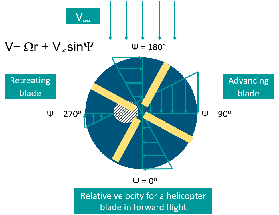
Rotary-wing VTOL systems operate in highly unsteady and complex environments comprising of unsteady, turbulent, and compressible flow. In forward/edgewise flight, the rotor experiences an asymmetry in velocity. The advancing side of the rotor sees an increased relative velocity, while retreating side sees reversed flow. This causes excessive lift on the advancing blade and a loss in lift on the retreating blade.
Rotor Dynamics
This imbalance of force on the rotor leads to a large rolling moment of the aircraft and large oscillatory stresses at the blade roots. To counteract this effect, modern rotorcraft designs have rotor hub articulation with hinges and are equipped with collective and cyclic pitch controls (pilot controls). The rotor system is at once responsible for generating the needed thrust, propulsive force, and moments to maintain the aircraft trim (in equilibrium) in steady level flight. While the collective control has the effect of increasing the rotor thrust, the cyclic pitch controls allow to vary the individual blade incidence angles, thereby alleviating the asymmetry in lift on the rotor. The articulated rotor head mechanism is an extremely complex, synchronized system of sub-assemblies in motion.
Check out this excellent animation on the rotor head mechanism to get insights into blade articulation.
In forward flight the blade flaps in response to the aerodynamic forces as it spins from 0 to 360 deg. The rotor articulation with the flapping hinge allows the advancing blade to move up, thus reducing the angle of attack and reducing the lift, while the retreating blade flaps down, thus increasing the angle of attack and thereby increasing the lift. This compensates for the asymmetry in lift. The flapping hinges also prevent the bending forces and rolling moments from transmitting to the fuselage.
The necessity for CFD-based aerodynamics prediction
For rotors operating in edgewise flight, the retreating blade may experience dynamic stall (at high speed) that is characterized by a rapid reduction in lift and reduction in pitching moment. As the forward speed increases, the advancing blade operates in transonic regime (due to increased velocity) and can encounter shocks, while the retreating blade can suffer from dynamic stall. Ultimately the dynamic stall is the limiting factor which puts a limit on the top speed on a helicopter.
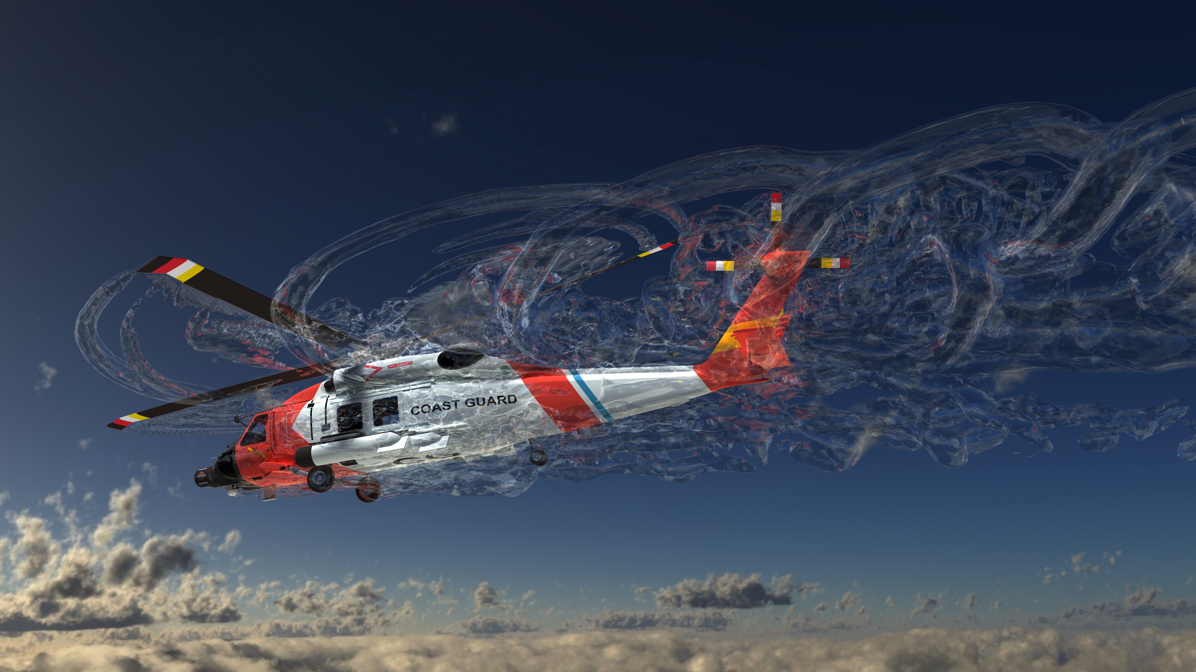
The wake of a moving rotor is complex causing significant aerodynamic interaction between the rotor system and the fuselage. The wake system is comprised of vortices which stem from the pressure-equalizing effects at the blade root and tips. They are more pronounced at the blade tips. These vortices induce a velocity field according to the Biot-Savart law. The vortices coming off from each blade interact with each other and with the following blades giving rise to blade-vortex and wake-vortex interactions and have a significant impact on the aerodynamic loading on the rotor. This directly impacts the performance of the helicopter and noise characteristics.
Wonder why those choppers make the “wop-wop” noise, thanks to the blade and vortex interactions! It is paramount for finite volume Computational Fluid Dynamics (CFD) methods using the right mesh, physics, and cell sizes to accurately capture these tip vortices without which the estimation of rotor performance is difficult.
An efficient rotor blade CFD/CSD coupling
Even if we capture the aerodynamics, a critical complexity in rotorcraft physics is that simulating the aerodynamics is not strictly an aerodynamic problem. This is because a rotor blade is slender and flexible and is therefore subject to elastic deformation in response to the aerodynamic loading. Added to this fact is that the linkages attached to the blade articulation are a complex mechanical system which needs to be accurately modeled.
Traditionally the rotorcraft comprehensive codes equipped with lower-order aerodynamics were used for estimation of key performance indicators such as thrust, hub moments as well as blade loads. However, accurate capturing of the aerodynamic loading is critical for obtaining the right blade loads, structural loads, and vibratory loads.
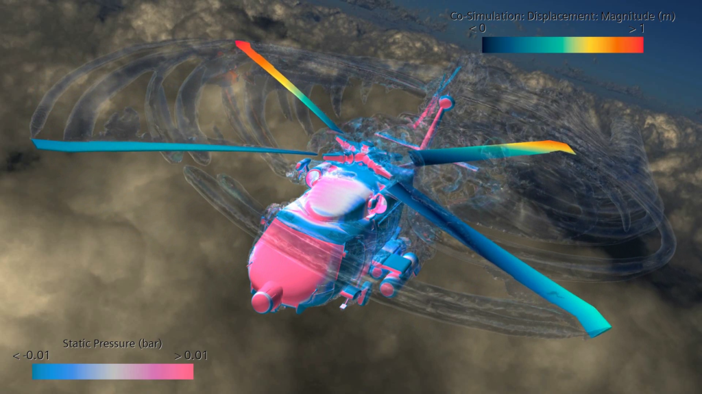
The starting point to model this complexity is rotor blade aeroelasticity – the coupling of the aerodynamics of spinning and flexing rotors and the dynamic structural response to aerodynamic loads. Using Simcenter STAR-CCM+ co-simulation capabilities the aerodynamic simulation can be coupled to structural dynamic simulation tools common in the rotorcraft industry (rotor blade CFD/CSD coupling).
Applications such as helicopters, advanced mobile vehicles, and wind turbines heavily rely on accurate prediction of complex interactions between aerodynamic forces and structural responses of their rotating blades (rotor blade CFD/CSD coupling). Hence, to gain insights into the behavior of the system and to accurately predict the performance of the rotor blades while reducing vibrations, high-fidelity aeroelastic simulations are key enablers for CFD engineers.
Simcenter STAR-CCM+ 2206 offers an industry-standard CFD/CSD methodology for iterative coupling process. The rotorcraft blade aeroelasticity capability in Simcenter STAR-CCM+ provides file-based co-simulation with rotorcraft industry-standard finite element-based multi-body structural dynamics tools such as RCAS, FLIGHTLAB, CAMRAD II, Dymore.
1- The elastic blade deformation and rotor trim are provided by the structural dynamics solvers through a motion file
2- Simcenter STAR-CCM+ reads in blade deformations data for an entire revolution (360 deg) and maps the blade displacements and rotations from the beam to the blade surface, thus morphing the shape of the blade. Each morphed blade is contained within an overset mesh region whose motion is automatically accounted for. The transient CFD analysis then computes the aerodynamic forces and moments on the deformed blades
3- At each time step, the aerodynamic forces and moments computed from the blade (through the transient CFD analysis) are automatically mapped to the beam representation of the rotor blades for a full revolution
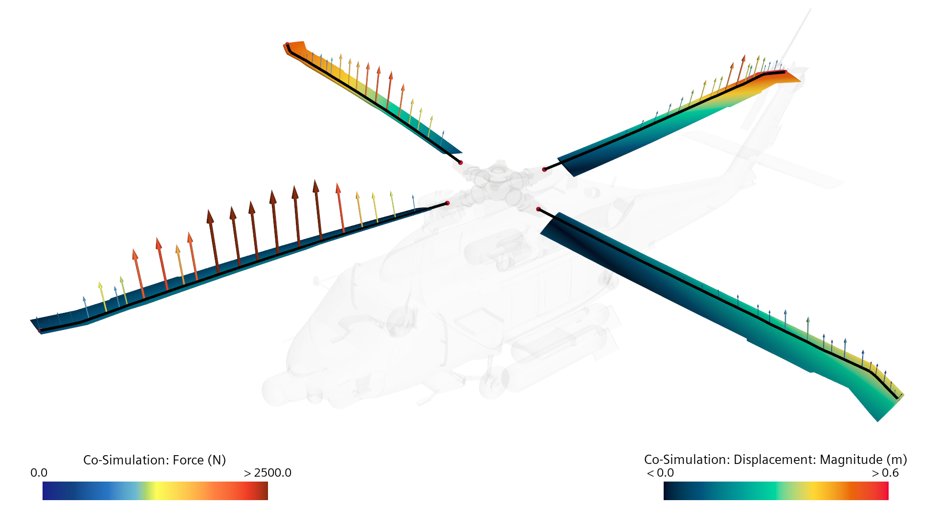
4- These sectional aerodynamic forces and moments are automatically written out to a file and are exchanged with the structural dynamics solver
5- The structural dynamics solver in turn computes the new blade deformations under the new aerodynamic loading
6- The RBA co-simulation iterates until the overall system is converged for both the structure and the flow enabling engineers to easily gain insights into the complex aeroelastic behavior of rotors.
RBA to the rescue!
The next generation of aircraft and advanced mobility programs need to meet strict targets to reduce vibration and noise, reduce cost and risk while expanding the flight envelope. It becomes essential to gain insights into the complex aeroelastic behavior of rotors at various conditions to improve upon and generate more efficient rotor blade and aircraft designs.
To save lives faster – be it a medical emergency or a rescue mission, the next generation of helicopters need to be less intrusive, operate quietly all while maintaining agility and safety. When the margin of error is small and lives are at stake – it becomes critical to do everything right, all the time.
One step towards that goal is to perform high-fidelity aeroelastic simulation and gain insights into obtaining safer, quieter, high-performing designs.
And so, the next time a “very task-saturated environment” hits the shores of this world, the next time Lt. Benjamin and his mates jump onto their helicopters, we can at least rest assured that they will be operating the best possible marvel of engineering – thanks to the hidden heroes of life-saving technology – Rotor blade CFD/CSD coupling engineers.
Additional Simcenter STAR-CCM+ 2206 top features will be revealed soon, keep watching!
In the meantime, discover how to collaborate effectively on multidisciplinary applications through Simcenter data exchange, a new feature in Simcenter STAR-CCM+ 2206.
References
- Potsdam, Mark, Hyeonsoo Yeo, and Wayne Johnson. “Rotor airloads prediction using loose aerodynamic/structural coupling.” Journal of Aircraft 43.3 (2006): 732-742.
- Bousman, William G. Putting the aero back into aeroelasticity. National aeronautics and space administration moffett field ca ames research center, 2000.
- Datta, Anubhav, Mark Nixon, and Inderjit Chopra. “Review of rotor loads prediction with the emergence of rotorcraft CFD.” Journal of the American Helicopter Society 52.4 (2007): 287-317.
- Marpu, Ritu P., et al. “Physics-based modeling of maneuver loads for rotor and hub design.” Journal of Aircraft 51.2 (2014): 377-389.