Revolutionizing heavy-duty transportation: Simulating a 700 bar Compressed Hydrogen Storage System for trucks with Simcenter system simulation
The transportation sector is today responsible for more than 20% of the CO2 global emissions. To achieve climate neutrality, we need to reduce transport emissions by 90% by 2050.
While we can see a clear trend of battery adoption for light duty vehicles, fuel cells powered by hydrogen seems to be a promising alternative for heavy duty applications.
The storage of hydrogen for mobility, remains however challenging when considering the high volume taken by this ultralight gas. To reduce this volume for transport applications, hydrogen is usually compressed to a pressure level of 350 or even 700 bar. Storage in a liquid form can also be considered but it requires to cool down to a very low temperature level and this technology is currently rather used for rockets and aerospace applications.
Considering gaseous storage systems, the high-pressure level requires specific tanks with solid structures but also H2 leak-proof materials sustaining high temperature variations, especially during defueling operations.
We propose in this article to present a model of a high-pressure hydrogen multi-tank system mounted on a truck tractor using Simcenter system simulation.
The defueling phase is simulated, and the tank temperatures especially monitored.
Description of the system
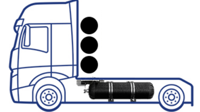
The system considered consists of 5 high-pressure type IV hydrogen tanks, 3 being positioned behind the truck tractor cabin, and 2 at both sides between the front and rear axles, as illustrated on figure 1 below.
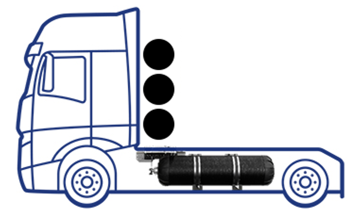
Figure 1: position of the 5 H2 tanks considered
Type IV hydrogen tanks have a non-metallic (polymer) inner liner and an outer full reinforced composite wrapping. Both characteristics enable to ensure the hydrogen tightness and to sustain high pressures. Such tank can be illustrated with figure 2:
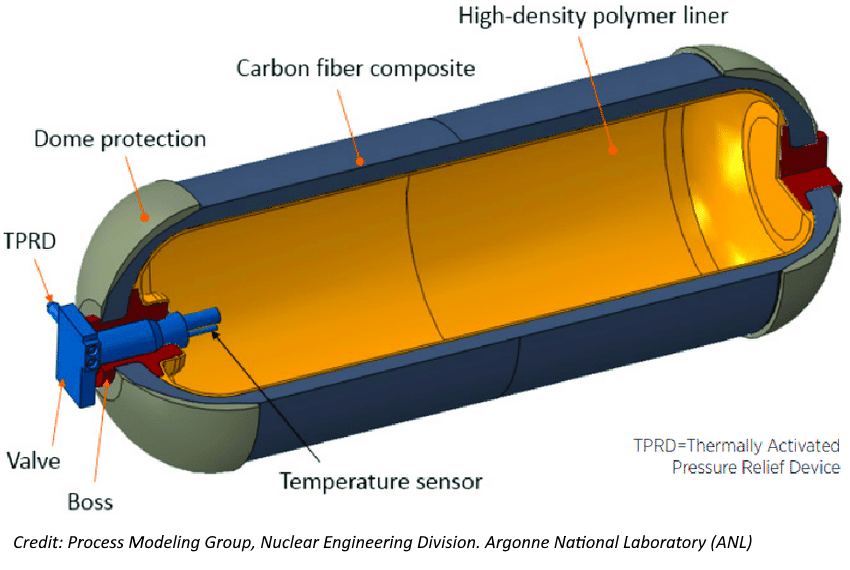
Figure 2: illustration of a type 4 hydrogen tank
The characteristics of the tanks are the following:
| Pressure | 700 | barA | |
| Liner material | HDPE = High Density Polyethylene – thickness | 5 | mm |
| Second layer | CFRP = Carbon Fiber Reinforced Plastic – thickness | 35 | mm |
| Outer layer | GFRP = Glass-Fiber Reinforced Plastic – thickness | 20 | mm |
| Tank length | 2000 | mm | |
| Tank inner diameter – side | 505 | mm | |
| Tank inner volume – side | Single tank | 400.6 | L |
| Total hydrogen mass – side | @15°C – 2 tanks | 29.9 | kg |
| Tank inner diameter – rear | 357 | mm | |
| Tank inner volume – rear | Single tank | 200.3 | L |
| Total hydrogen mass – rear | @15°C – 3 tanks | 31.9 | kg |
Table 1: H2 tanks main characteristics
Corresponding model
The system described above is modeled in Simcenter Amesim as illustrated by the following figure:
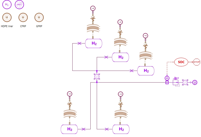
Figure 3: H2 tank system model in Simcenter Amesim
The 2 side tanks are represented in the bottom of the model, while the 3 rear ones are on the top. They are all linked together to a common volume followed by a pressure regulator set to 2.5 barA.
The mass flow source at the right side enables to define refueling or defueling (respectively positive and negative hydrogen mass flows as tank boundary condition) scenarios.
In the present article, defueling scenarios with different constant mass flows and different initial gas temperatures will be presented. These scenarios enable to see in which cases the minimum gas temperature (usually -40 degC), that can potentially damage the tank materials (i.e. liner), is reached.
The SOC component, i.e. State Of Charge, calculate during the simulation the remaining hydrogen mass out of the initial one in percentage.
Main assumptions & thermal considerations
- Gas Equation Of State (EOS):
At 700 barA and standard temperature, Hydrogen is supercritical and the compressibility factor is higher than 1.4, thus requiring to use a Real Gas Equation Of State to describe correctly its behavior. Different EOS are available in Simcenter Amesim for that purpose: Van Der Waals, Redlich-Kwong, Redlich-Kong-Soave, Peng Robinson, MBWR and Helmholtz.
The Redlich-Kong- Soave EOS (RKS) is used in this example.
- Thermal considerations: In addition to a good EOS, the modeling of the system thermal behavior is crucial in this example.
- For the inner part of the tank, free and forced convective exchanges between hydrogen and the inner liner are considered. Nusselt correlations are used to define the heat transfer coefficient. The Nusselt correlation for the free convection is a function of the Grashof and Prandtl numbers, the one for the forced convection, a function of the Reynolds number.
- Regarding the 3 layers of the tank material, radial conduction is considered using the thickness and the conductivity of each of them
- Regarding the convection from the outer skin of the tank to the ambient, a classical Nusselt correlation for forced convection around a cylinder is used with an ambient air speed of 5 m/s.
- Note that the initial gas tank temperature equals the ambient temperature
Simulated scenarios
3 defueling scenarios are simulated and compared. The following table summarizes the conditions of these scenarios:
| # | Ambient & H2 initial temperatures [degC] | H2 mass flow [g/s] |
| 1 | 15 | -3 |
| 2 | -10 | -3 |
| 3 | -10 | -1.5 |
Table 2: simulated scenarios
Note that for these scenarios, the simulation time stops when the SOC reaches 5% or a maximum time of 10 hours.
The results of the 3 simulated scenarios are gathered on the figure below (see associated scenario color) – the gas temperature is the one at the mixing chamber linking all tanks:
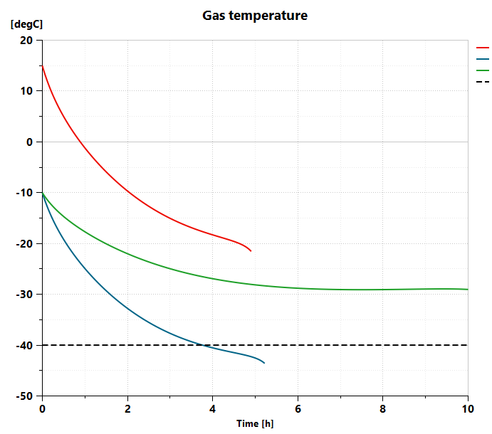
Figure 4: results of defueling scenarios – Gas temperature [degC]
![results of defueling scenarios – Gas Pressure [barA]](https://blogs.sw.siemens.com/wp-content/uploads/sites/6/2024/09/figure5.png)
Figure 5: results of defueling scenarios – Gas Pressure [barA]
![results of defueling scenarios – State Of Charge [%]](https://blogs.sw.siemens.com/wp-content/uploads/sites/6/2024/09/figure6.png)
Figure 6: results of defueling scenarios – State Of Charge [%]
The simulation stops at:
- 4h 54min for scenario #1
- 5h 13min for scenario #2
- 10h 00min for scenario #3
As can be seen in the results, the critical temperature of -40 degC is reached just before 4 hours for the second scenario, starting with an initial temperature of -10 degC with a hydrogen constant flow of 3 g/s.
Note that 3 g/s of hydrogen represents (using the Low Heating Value of H2) about 360kW of constant power. Considering a Fuel Cell efficiency of about 50%, this would mean that we could not sustain a constant power demand of 180kW for more than 4 hours in conditions of scenario #2. At that stage, the SOC is about 31%.
The 2 other scenarios are better, thermally speaking, since the minimum gas temperature reached is respectively -21.5 degC and -29 degC for scenarios #1 and #3.
We can also have a look at the material temperatures as presented in the following picture:
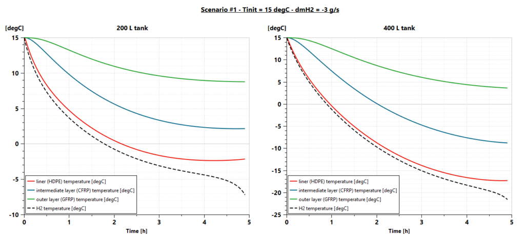
Figure 7: evolution of the tank materials and H2 temperatures for scenario #1
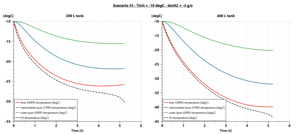
Figure 8: evolution of the tank materials and H2 temperatures for scenario #2
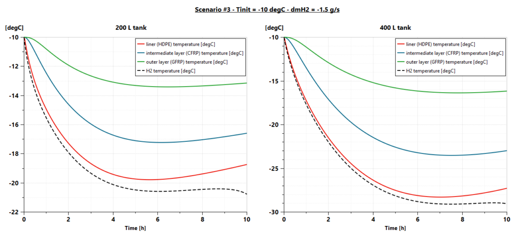
Figure 9: evolution of the tank materials and H2 temperatures for scenario #3
Note that such simulation is very quick since total CPU time for each scenario is much less than 1 second.
Conclusion and perspectives
We presented in this article the system simulation of defueling scenarios for a system of 5 high-pressure hydrogen tanks representative of a heavy-duty truck setup.
Such simulation can quickly give a good assessment of the temperature and pressure evolutions within the tanks as well as for the different material layers. This could help in sizing the tanks and determining the critical scenarios leading to temperatures that could be harmful for the tank structure.
Such model relies on standard thermal exchanges correlations and a recognized Real Gas Equation Of State. Refueling scenarios have been presented but the model can also be used for refueling ones. Refueling scenarios might require additional complexity like replacing the 0D volumes representing each tank by a stratified chamber, also available in Simcenter Amesim.
As a valuable complement we could take advantage of running more detailed 3D CFD analysis with Simcenter STAR-CCM+ on dedicated short scenarios in order to refine the thermal exchange correlations as well as the H2 flow pattern.
Learn more about Siemens Simcenter Amesim
Simcenter Amesim is the leading integrated, scalable system simulation platform, allowing system simulation engineers to virtually assess and optimize the performance of mechatronic systems.
Links to blogs
Links to webinars