Processing strain gauges for durability analysis. Tedious, right?
Let’s start with the why: why would you want to analyze strain gauge signals? The answer is easy: because when doing durability testing, you want to evaluate the fatigue behavior of your products. Strain gauge measurements capture the strain field on your component’s surface and allow you to understand whether it will endure the loading without fatigue failure.
Stress and Strain
But for fatigue analysis, we need to consider stress. Then why don’t we just measure it? Because we simply can’t. There is no physical sensor to directly measure stress.
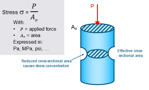
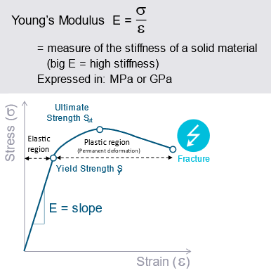
Stress is defined as a force acting on an area. So, you can measure a force and divide it by the area it is acting on. But often the area cannot be determined easily. If your component is behaving elastically under the applied loading, then the stress can be calculated as well from the strain by multiplying with the Young’s Modulus.
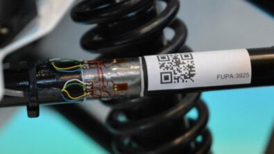
For measuring strain, on the contrary, we can use strain gauges. The most simple sensors are measuring strain only in one direction. This is fine if you already know the direction of the loading, which might be the case on a suspension link, tie rod, wishbone or trailer hitch. These are cases where you can determine, based on the geometry, if the load will mostly be transferred in one specific direction.
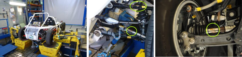
On larger surfaces like on fuel tanks, suspension knuckles or the exhaust system with multiaxial loading, this is not clear upfront and depends on the geometry and the combination of the loads acting on the component. In such a case you can use strain gauge rosettes, which will measure the strain including its direction in the plane.
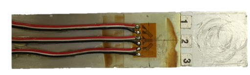
The rosette measures strain at three different angles (0°, 45°, 90° or 0°, 60°, 120°) to capture the strain tensor, i.e. the strain amplitude and the angle it is acting on. However, you basically get these three strain channels and it’s up to you to do the rest. And here is where it starts to get tedious – well, next to the gluing of strain gauges on the surface of course, but this is something our engineering services department can help you with.
Assess fatigue limits
To assess the fatigue behavior, you can compare the stresses with either the endurance limit (brittle materials) or the yield limit (ductile material). If no stress is above that limit, then your component is fine.
A more detailed durability analysis approach would be to calculate the actual life of your component for this loading. This involves Rainflow counting and Stress or Strain Life methods. We’ll come to that in a next article.
Let’s first focus on making sure that the loads are below a defined stress level. Looking at the simple strain gauge, there is only one direction and you can check if the derived stress is below that level. Easy! But if you don’t know the direction beforehand, you need to use a rosette. Now, what to do with the three strain channels you get from your measurement?
There are different approaches to finding the worst-case stress levels from the rosette. One way is to calculate reference stress and compare that to your stress limits, e.g. the Maximum Principal stress. It is calculating the amplitude of the stress no matter in what direction that amplitude occurs (i.e. angle in which the stress is acting might vary over time). If the Maximum Principal stress reaches or exceeds the stress limit or the Minimum Principal stress reaches below the negative stress limit, failure will occur.
Another way is to use the multiaxial stress state in the plane and project it to a set of angles, e.g. angles from 0° to 170° in 10° steps. This is called the Critical Plane Approach.
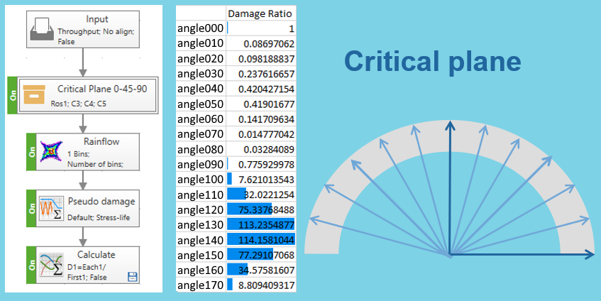
The fatigue theory assumes loading only in one direction, so we would look at all possible directions and check all of them for the stress limit. If the direction leading to the largest stress amplitudes is still under the stress limit, then the component is good to go. Next to checking the stress limits, the Critical Plane approach allows calculating damage for each angle.
Basically, this is all just math, and if you want to know more about the formulas involved, take a look at the Siemens Community
But how do we use those in practice to perform our fatigue analysis?
Using Simcenter Testlab Process Designer
Starting to enter all these formulas is already tedious. The worst part is that, usually, you are not dealing with only one rosette, but many of them.
Fortunately, there is an efficient way to deal with that in Simcenter Testlab Neo. I use the Process Designer to create a process that outputs the necessary information.
Let’s start with one rosette: in Simcenter Testlab Neo I can create a new process with pre-defined so-called Combined Methods that are prepared to process strain gauge rosettes. Combined Methods are like sub-processes that are built using the algorithms available in Process Designer. You can look at the details by double-clicking the Combined Method.
Now I only need to choose the measurement run that I want to process, select the three strain signals of the rosette in the Combined Method using the ‘Properties’ pane on the right, enter Young’s Modulus for the material that the strain gauge is glued on and run the process. The results include among others the Maximum and Minimum Principal stresses, which can be checked easily against the stress limit.
But what if I have a bunch of rosettes? Then I just add more Combined Methods, one for each rosette. where I select the three corresponding channels and the Young’s Modulus (as strain gauges could be glued on different materials).
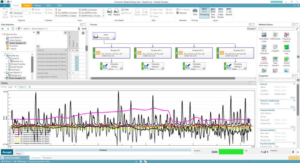
As you can see, setting up this process is rather fast and convenient, and the good part is that I don’t even have to do it over and over again. After I’ve created one process with e.g. 10 Combined Methods, I can save and reuse it later. Standardizing the rosette channel naming convention will help in making this process even easier to reuse. If I later use the process with fewer rosettes, then the unused Combined Methods are just ignored.
Using the Critical Plane Approach is as simple. Instead of the Rosette Combined Method, I use the Critical Plane Combined Method. I select the three channels and run the process. The result contains 18 directions from 0° to 170°. By overlaying them, I can check the limits.
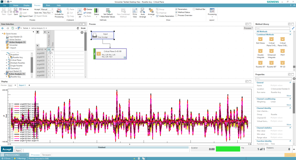
Now, why didn’t we calculate the angles from 180° to 350°? When we are checking the amplitudes of the stress, we check the positive values against the stress limit and the minimum values against the negative stress limit. Considering 0° and 180°, 10° and 190°, etc. are showing the same values, only minimum and maximum are switched. So, it’s perfectly fine to limit the calculations to 0° to 170°.
Conclusions
Now you see how easy and efficient the processing of many strain gauge rosettes in Simcenter Testlab Process Designer is:
- creating a process that covers multiple strain gauge rosettes by using prepared Combined Methods
- re-using that process combined with standardized channel names without further modifications
- assessing the fatigue limits easily, both Maximum Principal stresses and the Critical Plane approach
If you want to read more about strain gauge measurements, you can wait for my next article about calculating the Stress Life of rosettes or check out some of these links to learn more about durability testing:
- Introduction to Strain Gauges
- How to measure strain gauges with Simcenter Testlab
- Strength and Durability engineering solutions
- Online Seminar Series exploring the latest innovations in Durability Testing and Engineering
- SimRod experience: From Belgian blocks to vehicle durability testing (part 1)
- Heavy equipment durability testing: Living on the edge!