From DC to high frequency: Parasitic extraction with integral methods and surface impedance in Simcenter Flux
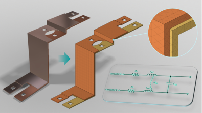
The electrification of transportation, and the electric vehicle industry in particular, is placing unprecedented demands on power electronics systems. Modern inverters must deliver high power density within increasingly compact form factors, while advances in semiconductor technology enable faster switching and higher operating frequencies (ranging from 10 kHz to over 100 kHz in certain applications).
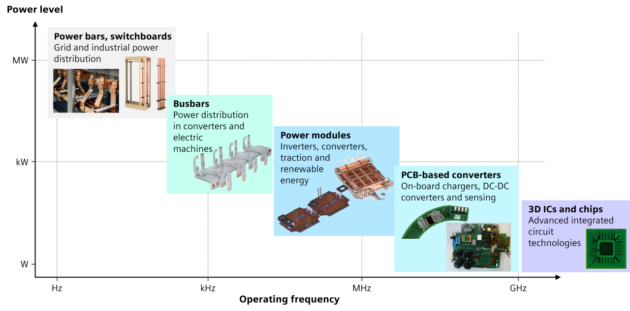
This technological evolution introduces a critical engineering challenge: parasitic effects. Excessive or poorly controlled parasitic inductance, capacitance, and resistance can result in:
- Voltage overshoots and ringing
- Electromagnetic interference (EMI)
- Reduced system efficiency and increased component stress
- Potential device failure
Accurately predicting these parasitic effects across the operating frequency range is essential for developing reliable and efficient power electronics systems. Engineers need a practical way to extract frequency-dependent parasitic parameters, evaluate design alternatives, and identify potential issues early, without excessive modeling effort and computational cost.
Why conventional finite element approaches can become challenging
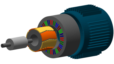
Finite element methods (FEM) have long been a cornerstone of electromagnetic simulation and continue to deliver reliable results across a wide range of applications. Electrical machines are a prime example, where electromagnetic fields can often be modeled effectively within a well-defined computational domain.
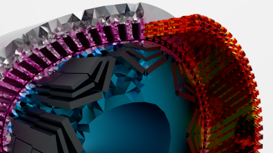
However, power electronics interconnections present different challenges. Large surrounding air volumes often need to be modeled, and conventional FEM requires the computational domain, including the surrounding air, to be meshed. Furthermore, components such as laminated busbars are often highly planar, with two dimensions significantly larger than the third. Accurately resolving electromagnetic behavior through the conductor thickness can require a highly refined 3D mesh. Together, these constraints can make FEM simulations time-consuming and memory-intensive, particularly for complex 3D geometries and high-frequency applications requiring fine mesh resolution.
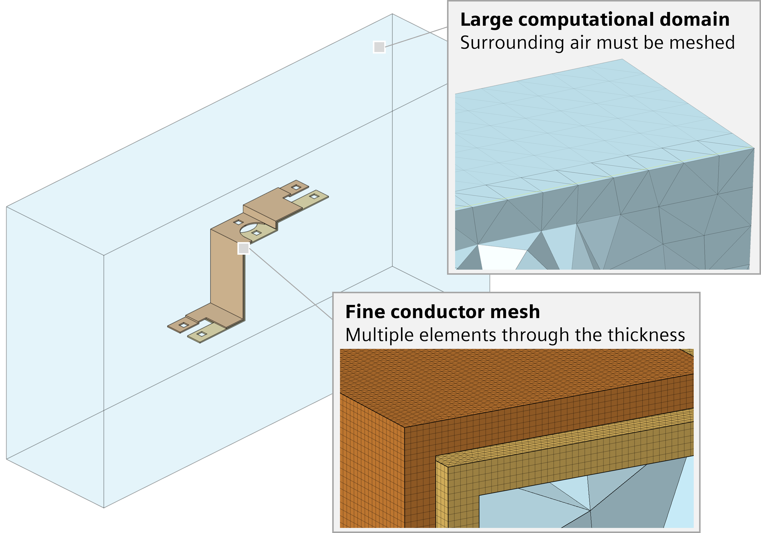
Beyond these computational challenges, extracting resistive, inductive, and capacitive (RLC) effects may require different electromagnetic formulations and simulation setups. Depending on the formulation and the parameters of interest, separate magnetic and electric simulations, followed by dedicated post-processing, may be necessary. For frequency-dependent parasitic characterization, this can increase both modeling complexity and computational cost. For applications such as laminated busbars, a more targeted numerical approach can therefore offer significant advantages.
Using integral methods for parasitic parameter extraction
Integral methods offer a compelling alternative. Unlike conventional FEM approaches, they require only the active regions, such as conductors, dielectric materials, and magnetic parts, to be meshed, eliminating the need to discretize the surrounding air. This simplifies model preparation and reduces the computational domain, allowing engineers to focus meshing effort on the components that drive parasitic behavior rather than on a large surrounding air region.
Among these air-mesh-free integral approaches, the partial element equivalent circuit (PEEC) method is particularly well suited to power electronics applications:
- Converts the electromagnetic problem into an equivalent electrical circuit containing resistive, inductive, and capacitive elements
- Enables extraction of parasitic parameters, including resistance, inductance, and capacitance
- Delivers efficient and accurate results across a broad frequency range under quasi-static assumptions
For geometries such as laminated busbars, where the active conductors occupy only a small portion of the overall computational domain, the PEEC method represents an especially effective modeling strategy.
Capturing skin effect without excessive mesh refinement
As operating frequencies increase, skin effect becomes increasingly important. Current tends to concentrate near the conductor surface, and the characteristic depth over which current density decreases is known as the skin depth. In copper at 1 MHz, the skin depth is approximately 66 μm.
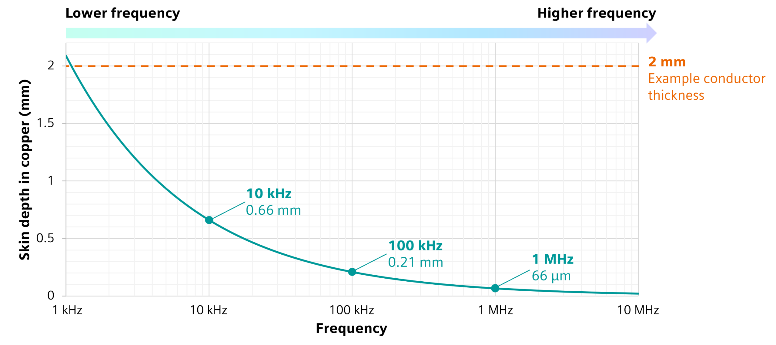
As shown in Figure 3, skin depth decreases rapidly with increasing frequency. For conventional volume-mesh approaches, accurately resolving this behavior requires sufficiently fine discretization through the conductor thickness, which can significantly increase computational cost at higher frequencies.
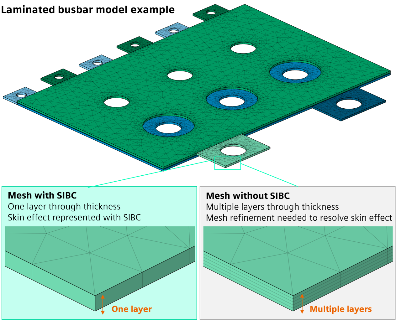
Simcenter Flux addresses this challenge through surface impedance boundary conditions (SIBC) combined with its integral quasi-static formulation. SIBC represents the high-frequency electromagnetic behavior of conductors through a surface impedance relationship, avoiding the need to explicitly resolve the skin depth with a highly refined volume mesh.
Figure 4 illustrates this difference for the laminated busbar model. With SIBC, a single layer through the conductor thickness can be used, while a conventional volume-mesh approach requires multiple layers to resolve the skin effect.
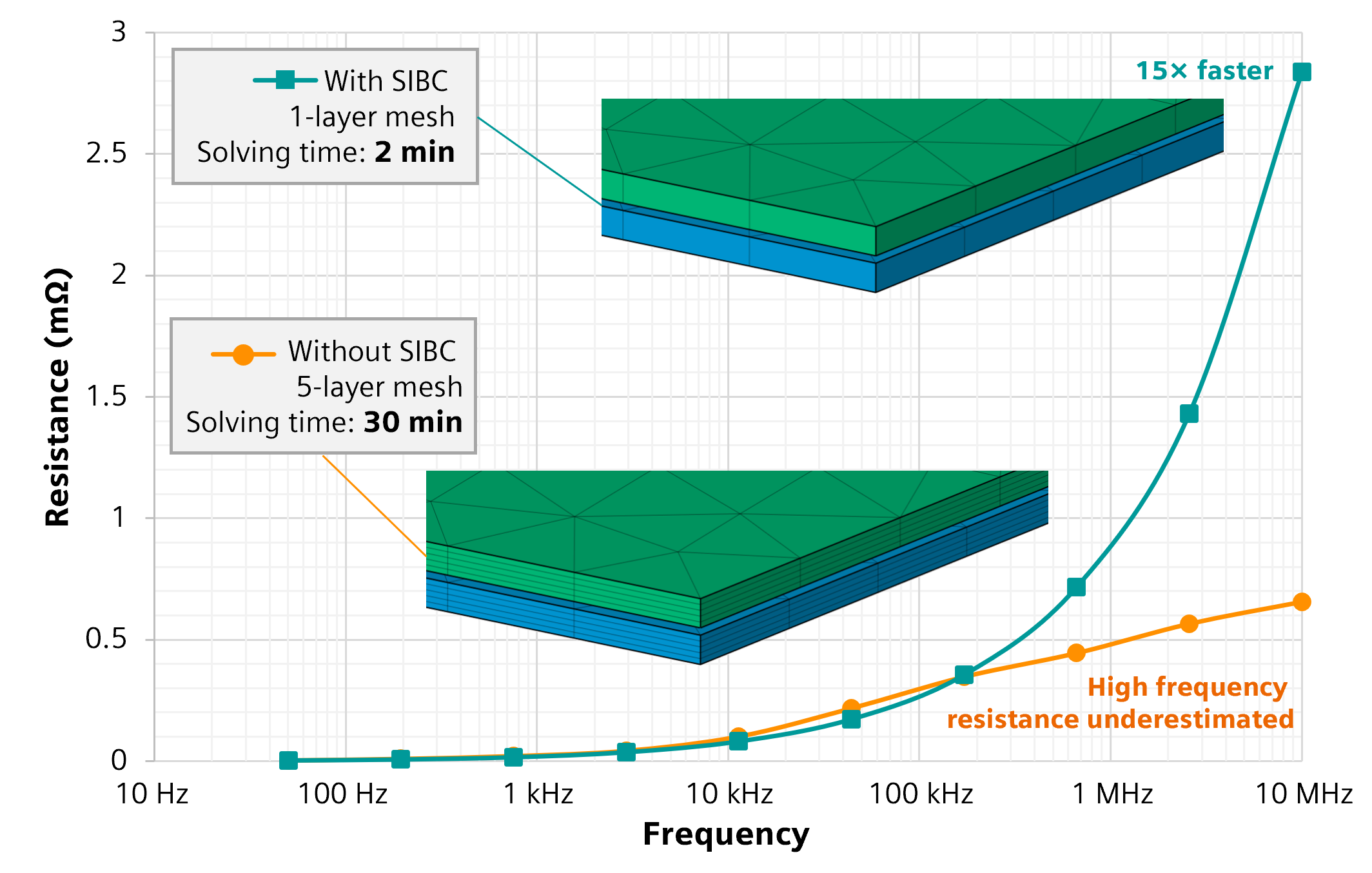
For this laminated busbar case, SIBC reduces the through-thickness mesh from five layers to one and cuts the simulation time from 30 minutes to 2 minutes—a 15× speedup—while capturing the high-frequency resistance behavior. These benefits are summarized in Table 1. The following section walks through the simulation workflow used to set up, solve and analyze this case in Simcenter Simlab with the Simcenter Flux solver.
| With SIBC | Without SIBC | |
| Mesh | One layer through each busbar | Five layers through each busbar |
| Simulation time | 2 minutes | 30 minutes |
| Accuracy | Skin effect captured through the surface impedance formulation | Resistance significantly underestimated at high frequencies |
| Mesh requirements | Standard, geometry-optimized mesh | Additional refinement required to resolve skin effect |
From CAD geometry to frequency-dependent parasitic parameters
Simcenter Flux combines its integral formulation with SIBC for efficient frequency-dependent parasitic extraction, within a structured workflow that takes engineers from imported geometry to impedance results. Through Simcenter Simlab, engineers can prepare the geometry, generate the mesh, configure the electromagnetic simulation, and analyze the results.
1. Import the busbar geometry
The workflow begins by importing the laminated busbar CAD geometry into Simcenter Simlab, where the model is prepared for electromagnetic simulation with Simcenter Flux. The imported geometry preserves the physical arrangement of the conductive layers and provides the basis for defining materials, insulation regions, and electrical connections.
2. Generate a mesh adapted to thin conductors
The geometry is discretized using wedge elements with controlled thickness and orientation. In Simcenter Simlab, mesh controls can be applied to relevant geometric features, such as the connection faces, before generating the extruded mesh with the EM Mesh tool. Because the surrounding air does not need to be meshed, computational resources can be focused on the active components and the geometric features that influence the extracted impedance.
3. Configure the parasitic extraction simulation
A parasitic extraction (PE) solution is configured in Simcenter Simlab using the Simcenter Flux solver. The frequency sweep is defined according to the intended operating range, and the previously generated mesh is assigned to the solution. Electrical ports are then configured to establish the relevant conductor connections, while material properties are assigned using the built-in material library. This setup enables Simcenter Flux to calculate the frequency-dependent busbar impedance across the specified frequency range.
4. Activate surface impedance boundary conditions
SIBC can be activated directly through the solver settings in Simcenter Simlab. Once enabled, the Simcenter Flux solver accounts for the high-frequency behavior of the conductors through a surface impedance relationship, without requiring additional mesh layers to explicitly resolve the skin depth.
5. Solve and analyze the results
After solving, engineers can directly evaluate frequency-dependent resistance, R(f), and inductance, L(f), using the post-processing tools in Simcenter Simlab.
The frequency-dependent resistance curve reveals the influence of skin and proximity effects, while the inductance curve provides insight into the magnetic coupling and current return paths. These results help engineers characterize the parasitic behavior of the laminated busbar across the frequency range of interest.
Turning extracted parameters into engineering decisions
The value of parasitic extraction goes beyond obtaining frequency-dependent resistance and inductance. By combining the PEEC method with SIBC, Simcenter Flux helps engineers turn these results into practical design insights, supporting decisions such as:
✅ Busbar optimization in power modules for electric vehicle applications
✅ EMI mitigation through improved understanding of current distribution and electromagnetic coupling
✅ Improved converter efficiency through more accurate parasitic characterization and informed design choices
✅ Earlier design validation before physical prototyping
This approach enables engineers to explore a broader design space, evaluating different geometric configurations and material choices within simulation timeframes compatible with industrial development schedules.
Conclusion
Integral methods, and particularly the PEEC method combined with surface impedance boundary conditions, provide an efficient approach to parasitic parameter extraction in power electronics. In Simcenter Flux, these capabilities simplify meshing, reduce simulation time, and enable engineers to characterize frequency-dependent parasitic behavior across the operating range—supporting faster evaluation of design alternatives earlier in the development process.
Ready to explore these capabilities? Follow the step-by-step tutorial to model laminated busbars using the Simcenter Flux solver with the PEEC formulation and SIBC. More capabilities and enhancements are available in Simcenter Flux 2026.1.