Efficiently Optimize Vehicle Durability With Virtual Tests Using Internal Loads
Durability is a crucial vehicle performance attribute
During the design and prototyping phase of vehicles (passenger cars, sports cars, other ground vehicles, …), multiple numerical and experimental analysis are performed to improve the predictions on the durability of components. Durability is defined as the ability of a part to withstand damage and remain functional without requiring excessive maintenance. It is possible to efficiently optimize vehicle durability with virtual methods and high-end test methods. Refer to [1] for a historical overview of fatigue (with focus on the methods, often derived from experiments). Controlling the fatigue phenomenon in suspension assemblies constitutes an important step in the development of modern vehicles. After driving large distances, fatigue cracks may occur in the components, leading to potential failures and possible safety hazards that require the vehicles to be repaired.
In every vehicle, suspension components are continuously exposed to dynamic loads of various amplitudes. Durability prediction of suspension systems has always been a critical parameter in quest of more performance, efficient, and safer vehicles. A more accurate estimation of applied loads on the vehicle can lead to a more accurate lifetime prediction for vehicle suspension parts.
Efficiently Optimize Vehicle Durability thanks to Virtual Durability Testing
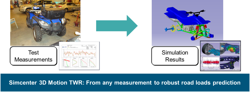
One way to verify the durability performance is to perform extensive field tests on public roads and test tracks. During these field tests, the service loads at some specific points of the vehicle are measured. Those service loads can be accelerations, forces or displacements, and are referred to as target signals. The field tests are instrumental for analyzing and optimizing the vehicle durability and comfort, but these physical tests are very expensive, time-consuming and sometimes uncomfortable for the test driver who is intended to drive hours on severe road conditions. An alternative is to simulate the measured loads in a laboratory environment [2]. This way, the service load simulation approach starts from only one test drive on the terrain or road, during which the target signals are measured, and is then reproduced on a multi axial test rig [3]. The underlying methodology is the Time Waveform Replication (TWR) approach [3], which allows to perform accurate and fast service load simulations on multi axial durability test rigs [4]. Figure 1 shows the Simcenter 3D Motion TWR approach, yielding robust road loads predictions from any measurement.
TWR Methodology: Accurate road loads estimation enabling vehicle design for durability
The Time Waveform Replication (TWR) methodology tries to match a linear model to represent a nonlinear reality. The most common technique is based on linear frequency domain modelling, using an averaged frequency response function (FRF) obtained in the initial system identification phase [3]. This approximates the nonlinear suspension system with a set of linear FRFs. Mathematically, the FRFs describe the vehicle as a multi-input/output (MIMO) system [6]. Using Simcenter 3D Motion TWR, the control signals for the actuators are computed for the test rig setup. The aim is to replicate the loading conditions of the road, on a test rig. Usually, the wheel forces in different directions are applied to the test rig. The challenge is to recreate the correct loads as obtained from a real road. The TWR process adopts an iterative process to minimize (over multiple iterations) the differences between the road targets and the systems responses [4].
Simcenter 3D Motion TWR Solution
Especially for off-highway ground vehicles applications, accurate loads prediction is important early in the development cycle, when high fidelity tire models and digital road profile data are not yet available. Simcenter 3D Motion TWR enables the prediction of accurate loads through a Hybrid road approach by mimicking test conditions, even when tire and road data is not readily available. This allows vehicle manufacturers to efficiently optimize vehicle durability.
Simcenter 3D Motion TWR is an application in the Simcenter 3D portfolio which leverages the multibody dynamics capabilities in Simcenter 3D Motion. Figure 2 shows the capabilities and process workflow in Simcenter 3D Motion TWR. Test conditions can be captured through “Hybrid” technology, as a good balance between results accuracy and calculation efficiency.
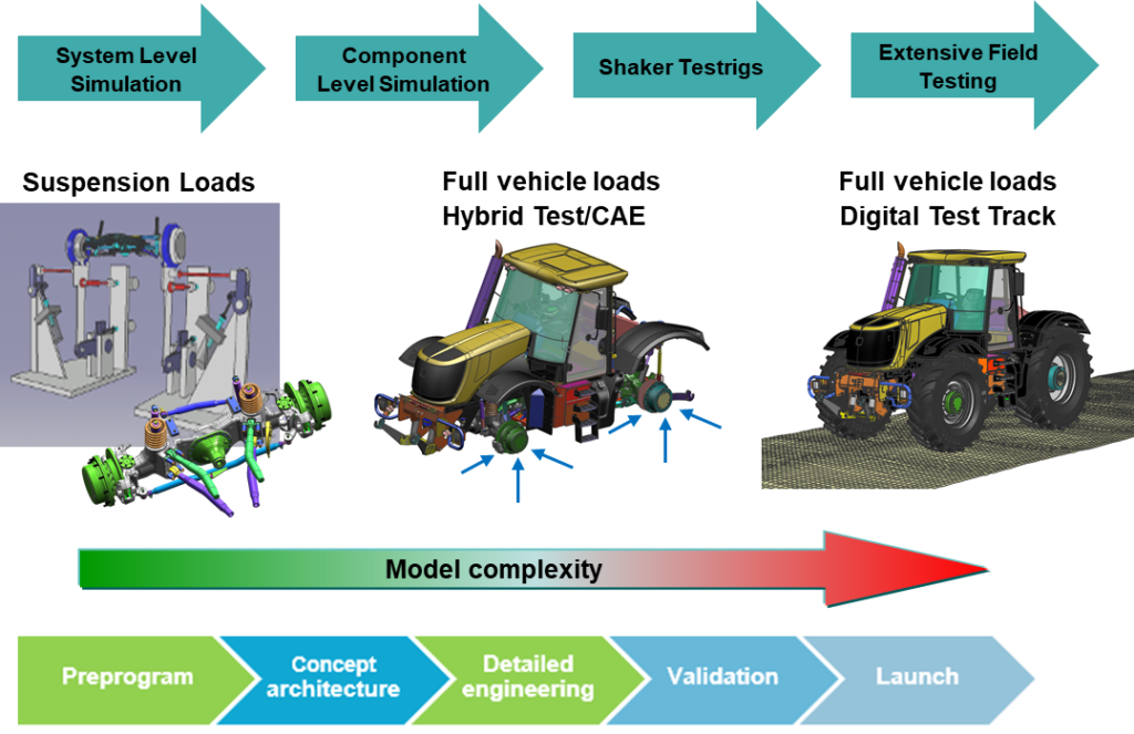
Simcenter 3D Motion TWR allows the user to build a virtual test-rig, calculate the frequency response function of a given multibody system, specify target signals, filter and condition the signals, and ultimately produce conditioned drive signals via an iterative solution process [7].
To efficiently optimize vehicle durability in line with the TWR approach, Simcenter 3D Motion TWR uses a simplified multibody simulation model. Complex elements normally included in a full vehicle model like a tire, a digitized road, or driver model are not necessary, since the driving functions computed in Simcenter 3D Motion TWR are applied at the wheel center. The simulation setup resembles a durability test rig. This is why it is not necessary to reproduce the complete road test with a digitized road and a driver model. Another advantage is that the drive signals can be re-used in a new vehicle development project.
Proposed Innovation: Extra sensor signals for an improved TWR prediction
Although the quality of the estimated responses for external loads on the vehicle can reach a high level of accuracy along TWR iterations, replicating internal loads of the suspension systems represents an additional challenge. The complexity of the interaction between internal components makes the estimations more difficult. However, the durability estimation of the components would be more accurate if these internal loads are also accurately estimated.
To cope with the convergence of internal loads in the TWR process, a solution would be to include the internal loads as targets to be replicated. The effect of internal load inclusion in the TWR process has been numerically investigated [8]. Based on different loading scenarios and sensors layouts, this blogpost explores the possibility of considering extra sensor signals, such as internal forces, and assesses the impact on the accuracy of results estimated with Simcenter 3D Motion TWR.
Case Study Description: SimRod vehicle
The vehicle model used in this case study is called SimRod. SimRod is based on the eRod vehicle that is a fully electric vehicle manufactured by the Swiss company KYBURZ. This two-passenger car weighs around 600 kg and it is propelled by a rear-mounted electric motor. The vehicle can achieve a top speed of 120 km/h using a 45 kW/140 Nm electric motor. This car is instrumented and equipped with measurement sensors.
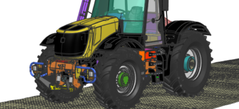
The light chassis of the vehicle is made of interconnected tubular rods, reinforced by plates in some specific locations. The tubes and plates are modeled respectively with beam and shell elements. The stiffness of the FE model is updated based on multiple experimental modal analysis performed on the real car and a digital twin is available for performing simulations [9][10]. A rendered view of the digital model of SimRod is illustrated in Figure 3.
Case Study Approach: Simulation Cases for the SimRod vehicle
The combination of digital models of the vehicle and the road makes it possible to simulate the dynamic behavior of the suspension systems in a multibody simulation framework. Now let’s efficiently optimize the vehicle durability performance. In a first simulation, the vehicle ran along a rough road with a controlled speed, as shown in Figure 3. The sensor data is stored as targets in time domain.
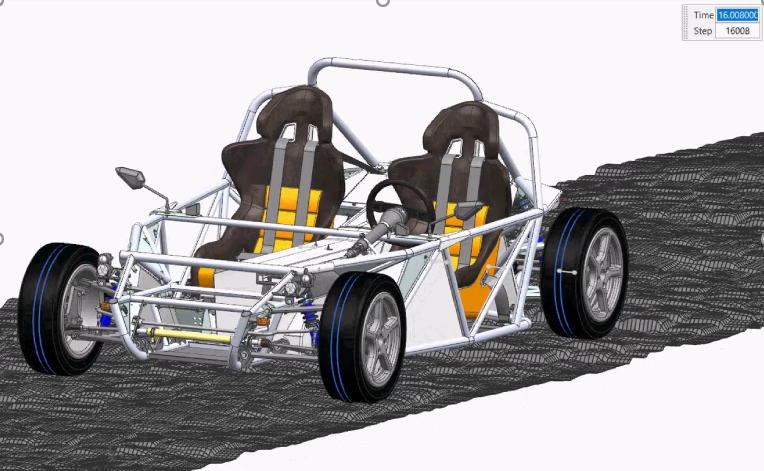
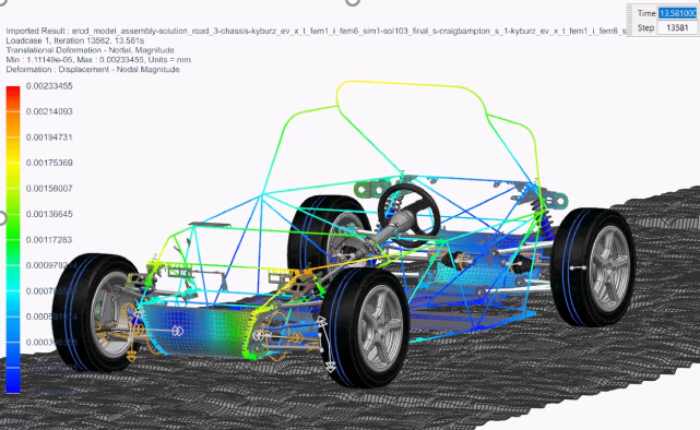
Figure 3b (Right) The flexible chassis is modeled with beam and shell elements
In a second simulation, the vehicle’s chassis is fixed to a digital test rig support and the wheel hubs are excited by multi-axial actuators. System identification techniques in frequency domain allow to estimate a reliable FRF model of the SimRod vehicle on the test rig. Once the model is identified, the targets obtained in the first simulation are fed into the TWR process. This results in the computation of a set of drives that reproduce the road loading conditions on the vehicle.
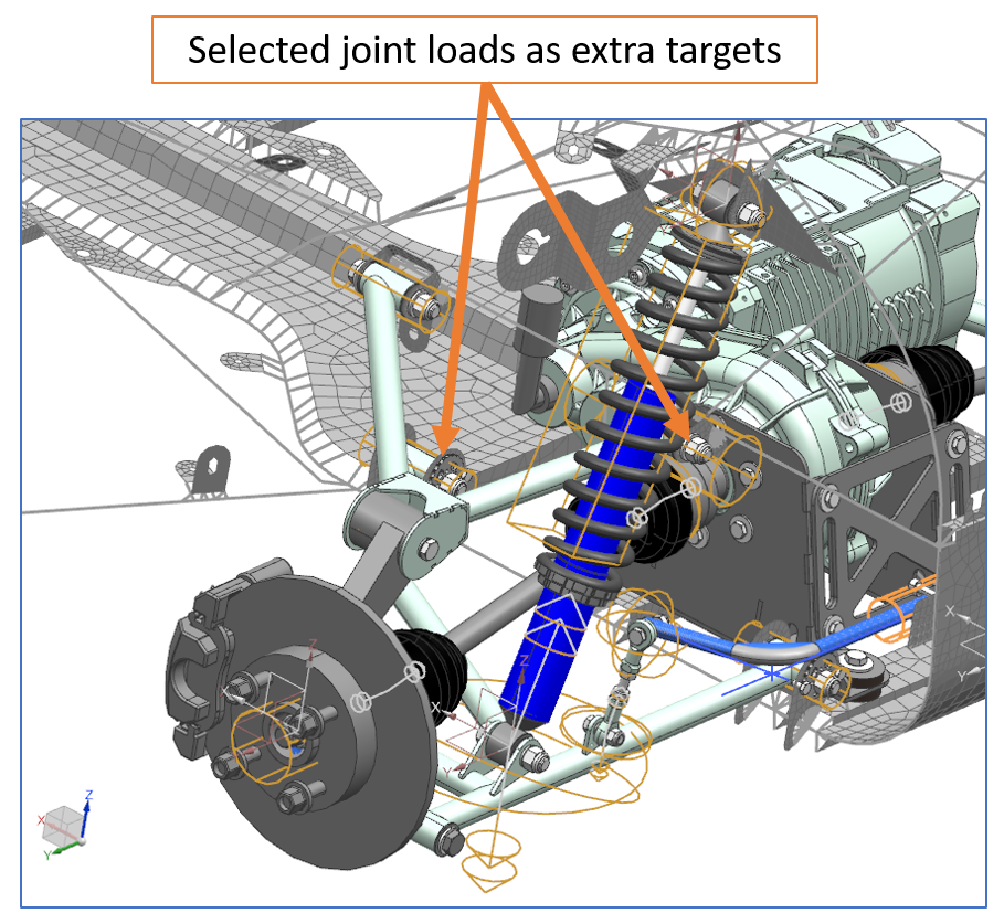
Depending on the choice of sensor layout, different set of channels are processed in the TWR analysis. Two sensor layouts have been considered in the research [8]: (1) A conventional layout including mainly the external forces; (2) An augmented layout in which additional internal forces are accounted for. The strategy behind the numerical analysis is to compare these layouts in terms of TWR estimation accuracy. The extra sensor channels used in the augmented layout are active forces at the joints of the upper/lower control arms; their locations are shown in Figure 4. These are the forces that the suspension exchanges with the chassis at the joint interfaces. The effect of these extra channels on the quality of TWR estimations is assessed. A feasibility study has been performed on a rough road [8].
Case Study Results: Evaluating the effect of extra sensors on the SimRod vehicle
One representative result of the study, highlighting the value of the new idea with additional internal sensors, is shown in this section. Further results have been published in [8].
In order to obtain an overall evaluation of the benefits in using augmented sensor layout, the RMS of the mismatch between targets and estimated responses is computed. Two additional metrics are used in order to limit the effect of amplitude differences between channels. In a first attempt, the RMS of each channel is normalized by its own maximum amplitude. This value is represented in the comparison tables as “RMS normalized individually”. Then, a second metric is proposed, which consists of normalizing channels within their category. For example, all vertical forces belong to a group and the RMS values are normalized by the maximum amplitude of the channels in that group. This parameter is represented in the results as “RMS normalized to group max”. As the main purpose of the analysis is to estimate the durability of the components, the pseudo-damage value is introduced as a fourth comparison metric. Combined with the previously calculated normalized RMS values, it can become a good indicator of the signal estimation quality. The objective of this study is to evaluate if the pseudo-damage resulting from the test rig simulations with extra targets is closer to the computed damages of the road simulation.
In Figure 5, the comparison between the results of the TWR process with the conventional and augmented (with force) layouts are illustrated. These results correspond to locations where extra force sensors have been virtually placed. The effect of adding internal forces (in lateral direction) of the upper control arm seems beneficial for the TWR response computation. Both the RMS and damage indicators have improved. When internal forces are added, the analysis of the TWR results shows improvements in the response estimation quality of TWR at sensor locations [8].
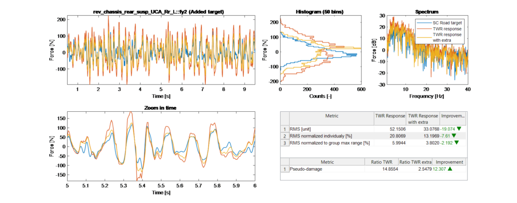
By analyzing the entire set of sensors, it was observed that the sum and the average values of the improvement factors for all channels confirm that the use of additional targets in the TWR process results in an overall better replication of damages. In particular, the improvement is more pronounced for the force signals that were used as extra targets. With Simcenter 3D Motion TWR, especially when enriched with additional sensors, one can efficiently optimize the vehicle durability performance. An extended report on these results has been published [8] in the proceedings of the ISMA 2020 conference in Leuven, Belgium, Sept. 7-9, 2020.
About the ENDURANCE Project
This research has been performed in the frame of the R&D project “ENDURANCE” (Efficient durability testing and vehicle usage evaluation), funded by VLAIO (Flemish government agency Flanders Innovation & Entrepreneurship), which has been coordinated by Siemens (Siemens Digital Industries Software, Belgium) with research partner KU Leuven LMSD. The ENDURANCE project has aimed at researching advanced durability simulation and testing tools, to efficiently optimize vehicle durability, whereby innovative solutions for the most crucial parts and major bottlenecks of the “V-shaped” durability design cycle are targeted.
Acknowledgements
This blogpost is based on results achieved by Ali Rezayat and colleagues within the R&D project “ENDURANCE” (“Efficient durability testing and vehicle usage evaluation”, VLAIO Agreement Number IWT.150958, Oct. 2016 – Sept. 2019). Siemens Digital Industries Software (DI SW) gratefully acknowledges VLAIO (Flemish government agency Flanders Innovation & Entrepreneurship) for the support of “ENDURANCE”, which has been coordinated by Siemens DI SW with research partner KU Leuven, enabling to efficiently optimize vehicle durability.
Siemens Digital Industries Software – Solution Offering
- Siemens Digital Industries Software, “Strength & Durability Solutions for Automotive Performance Engineering”, Retrieved 2020.
- Siemens Digital Industries Software, “Finding the longest lasting design, faster – Designing durable vehicles with simulation using Simcenter 3D”, White Paper, Retrieved 2020.
- Siemens Digital Industries Software, “Simcenter 3D Motion”, Retrieved 2020.
- Siemens Digital Industries Software, “Carry out road load prediction for durability simulation in hours instead of days“, Webinar 2021.
References
[1] Siemens Digital Industries Software, “History of Fatigue”, Community Article, August 29, 2019.
[2] C.J.Dodds, A.R. Plummer, “Laboratory Road Simulation for Full Vehicle Testing – A Review”, SAE Paper 2001-26-0047, 2001
[3] J. De Cuyper, D. Coppens, C. Liefooghe, J. Swevers, M. Verhaegen, “Advanced Drive File Development methods for improved Service Load Simulation on Multi Axial Durability Test rigs”, Proc. Acoustics and Vibration Asia, Singapore, Nov. 11-13, 1998
[4] A. Toso, B. Darnis, B. Prescott and J. De Cuyper, “Integration of Time Waveform Replication Process in a Multibody Software for Reverse Load Identification”, in ASME Conference, Washington DC, USA, Aug 28-31, 2011.
[5] Nissan Technical Centre Europe, “Implementing end-to-end Simcenter solutions for test-based durability engineering”, Customer Story on Siemens website, 2019.
[6] B. Cornelis, A. Toso, W. Verpoest and B. Peeters, “Improved MIMO FRF estimation and model updating for robust Time Waveform Replication on durability test rigs”, in International Conference on Noise and Vibration Engineering, vol. 1, pp. 759-774, 2014.
[7] M. Bäcker, Thomas Langthaler, Markus Olbrich, Helge Oppermann, “The Hybrid Road Approach for Durability Loads Prediction”, SAE International, 2005-01-0628.
[8] A. Rezayat, M. Grottoli, Y. Lemmens, T. Tamarozzi, C. Liefooghe, “Influence of internal loads on the accuracy of durability tests of a vehicle on a test rig”, Proceedings of ISMA 2020, Leuven, Belgium, September 7-9, 2020.
[9] G. Frans, “SimRod experience: From Belgian blocks to vehicle durability testing”, Simcenter blogpost, January 22, 2020.
[10] J. Debille, “SimRod experience: Mode shapes in modal analysis need test-calibration”, Simcenter blogpost, April 30, 2020.


