Don’t wait: Boost your heat pump’s efficiency with low GWP refrigerants before regulations hit
Introduction
Statistics indicate that 30% of the global generated power is consumed by the building sector. Today the energy efficiency in buildings stands out as a laggard and in the context of a growing climate crisis, the urgency to transition towards sustainable energy solutions has never been greater.
The situation is even worsened by an urban population that is quickly increasing in most developing economies; thus, ensuring that new buildings meet high performance standards for efficient heating and cooling presents a huge opportunity to limit future strains on energy supply and emissions.
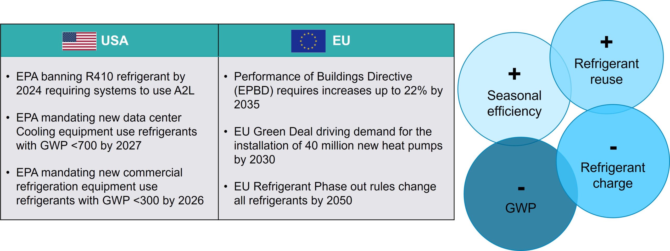
Reversible heat pumps, providing both heating and cooling, have emerged as a key technology in this transition. Their high energy efficiency and ability to utilize renewable energy sources make them an essential technology for reducing greenhouse gas emissions in residential, commercial, and industrial buildings. However, the environmental benefits of heat pumps can be compromised using refrigerants with high global warming potential (GWP).
Refrigerants play a critical role in the operation of heat pumps and many traditional options have the potential to significantly contribute to the climate change if released into the atmosphere during manufacturing, installation, maintenance or decommissioning. This has driven a global push toward the adoption of low-GWP refrigerants, which align with international climate agreements and help mitigate the environmental footprint of HVAC systems.
This article introduces an effective workflow for the design and optimization of residential reversible heat pumps with low-GWP refrigerants leveraging Simcenter Amesim system simulations.
The design process starts with the definition of the heating and cooling requirements from a transient thermal model of the residential building.
Subsequently, the system simulation of the HVAC system is performed in three sequential steps using the most relevant Simcenter Amesim models based on the simulation objectives:
- Definition of the thermodynamic cycles to achieve optimal operating cooling and heating conditions, considering the hottest and coldest days of the year
- Design of individual components, such as heat exchangers, compressor and valves, to meet the previously defined target conditions
- Final validation and verification of the HVAC system performance in both cooling and heating mode
Finally, the HVAC system is virtually integrated into the building for comprehensive simulations for the final verification of the control strategies and interactions of subsystems’ dynamics. This blog focuses on an air-to-air reversible heat pump for a residential house, although the workflow can be applied to any heat pump technology and application.
Residential building heat pump simulation with Simcenter Amesim
The definition of cooling and heating requirements of a building is crucial for designing an efficient HVAC system. Simcenter Amesim allows engineers to simulate the thermal behavior of buildings, considering external and internal heat gains, building materials and surfaces, fresh air changes and ambient conditions.
Engineers can simulate the thermal response of the building to external conditions and evaluate the impact of internal heat loads such as occupants, lighting, and equipment allowing to compute the exact cooling and heating power demand.
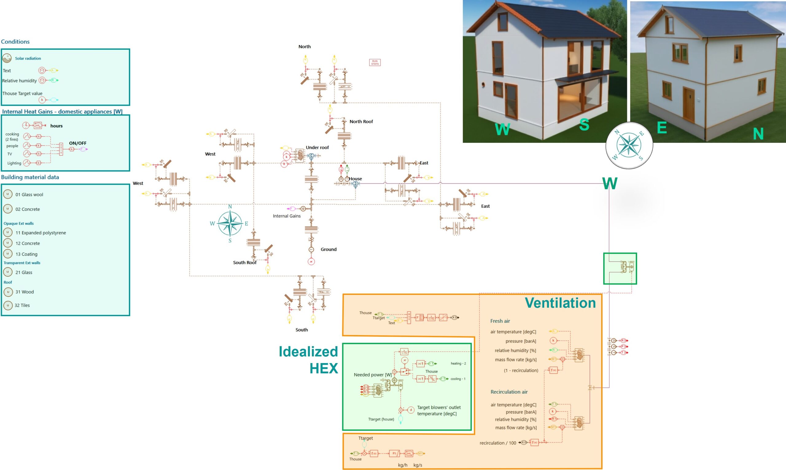

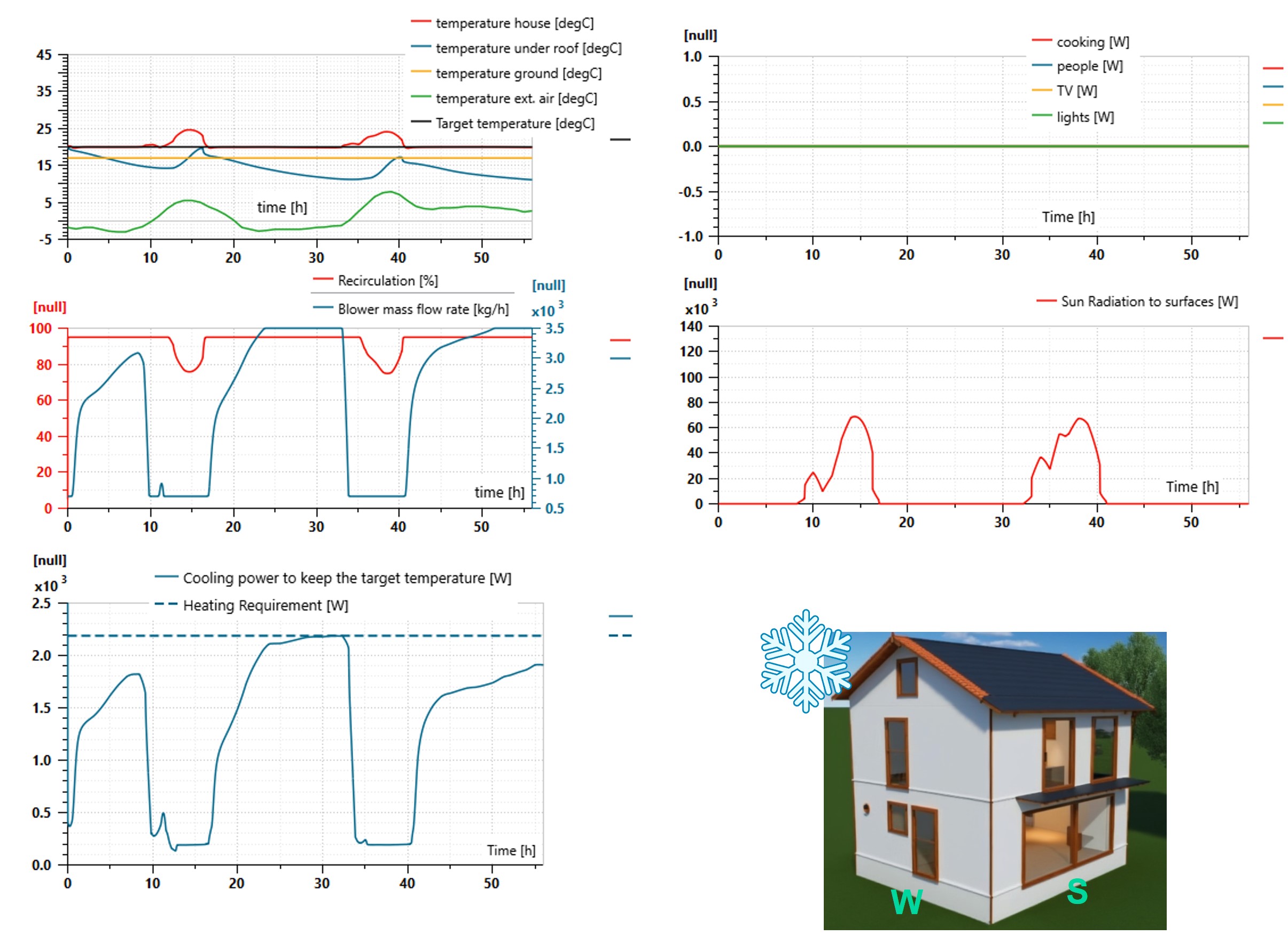
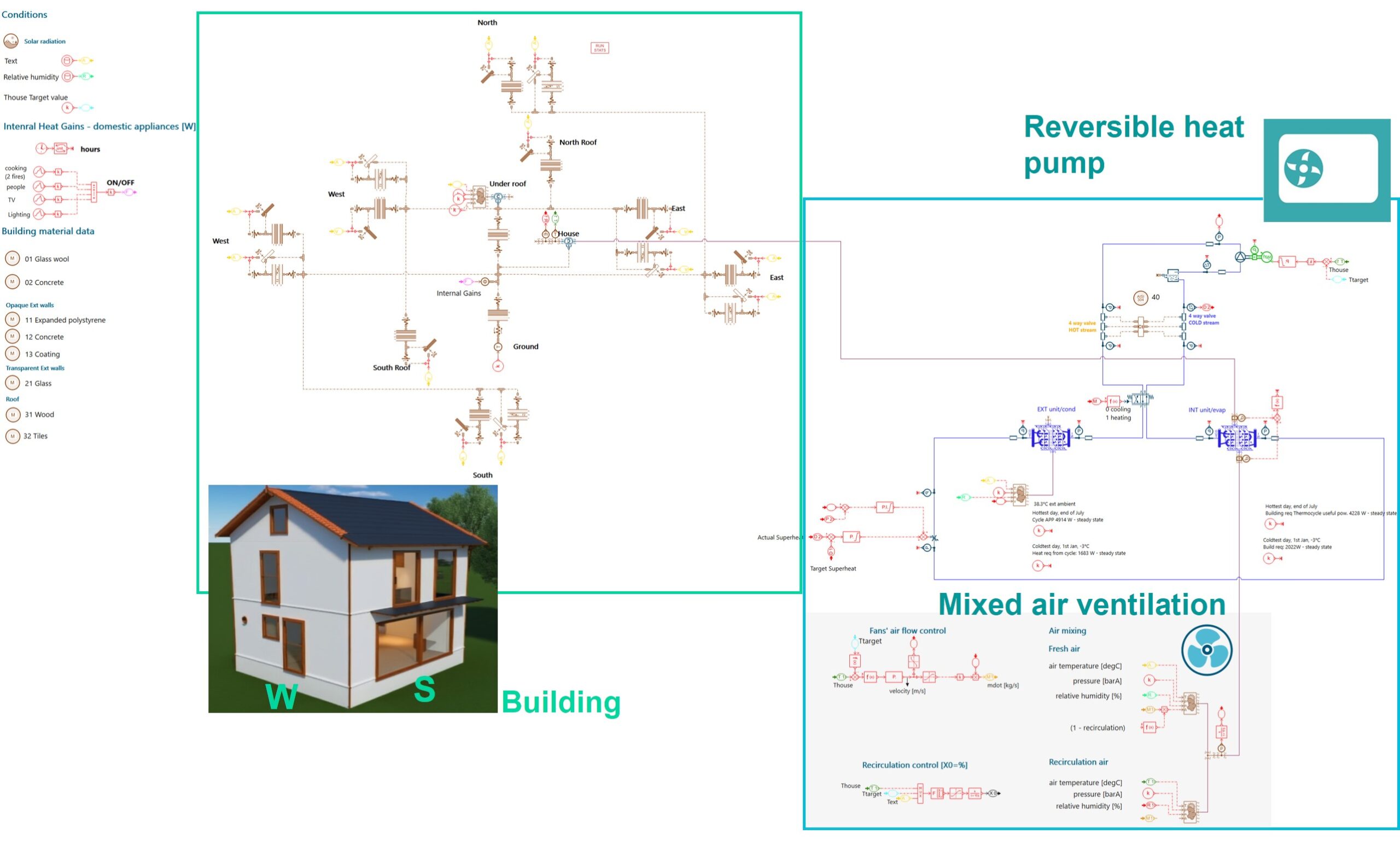
Figure 2 – Two-zones thermal model of the residential building and simulation results
The Simcenter Amesim transient thermal model of the residential house in Figure 1 includes:
- Two air volumes for the house and the attic.
The energy conservation equation is applied to these volumes to calculate the transient evolution of the temperature and humidity. - Building surfaces:
- Opaque surfaces (walls) with multiple layers including insulation. The thermal capacitance of each layer, the resistances (contact and linear) and the absorption of solar radiation are represented.
- Transparent surfaces (windows) with multiple layers including air gap.
In addition to opaque surfaces, transparent surfaces account for solar radiation transmitted inside the building.
- The indoor blower mixing both fresh and recirculation air and its control system.
- Ambient conditions.
The residential building is in a temperate climate zone and climatic data from past years can be used to set the right boundary conditions (ambient temperature, relative humidity, cloud coverage) to the simulation model. - An initially idealized heat exchanger is used for the indoor unit together, with a control system ensuring a predefined outlet air temperature for both heating and cooling operation modes.
This comprehensive building simulation helps in determining the requirements and then in properly sizing the HVAC system to exactly meet the building’s specific needs.
HVAC system simulation with Simcenter Amesim
Starting with the building requirements at the specific location, the design of a reversible heat pump begins by defining the target thermodynamic cycles in cooling and heating modes, with the chosen refrigerant. Next individual components are designed and the appropriate refrigerant charge determined. Finally, the closed-loop controlled system is developed to regulate the compressor speed, indoor and outdoor fans, and the electronic expansion valve, ensuring the system meets the required heat power and maintains the target indoor temperature of the house.
Defining the target thermodynamic cycles
Simcenter Amesim offers an easy-to-use tool to define and analyze thermodynamic cycles for refrigerant loops, before any time-simulation is run.
Based on the target cycles, engineers can quickly compare different refrigerants, including low-GWP options like R290 (propane), in terms of performance and select the most suitable one.
Each (cooling and heating) cycle is defined by some key parameters:
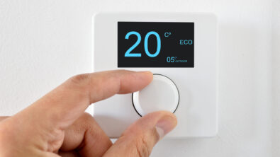
- Evaporating and condensing temperature are selected based on the most severe ambient conditions (in summer and winter) at the building location and the target indoor comfort value. Nowadays standards recommend comfort temperature ranges such as to reduce the energy consumption; consequently, the target is set at 20°C during winter and 24°C during summertime.
- Superheat and subcooling
- Isentropic efficiency of the compressor
- The required cooling and heating power for the indoor unit, provided by the thermal model of the building.
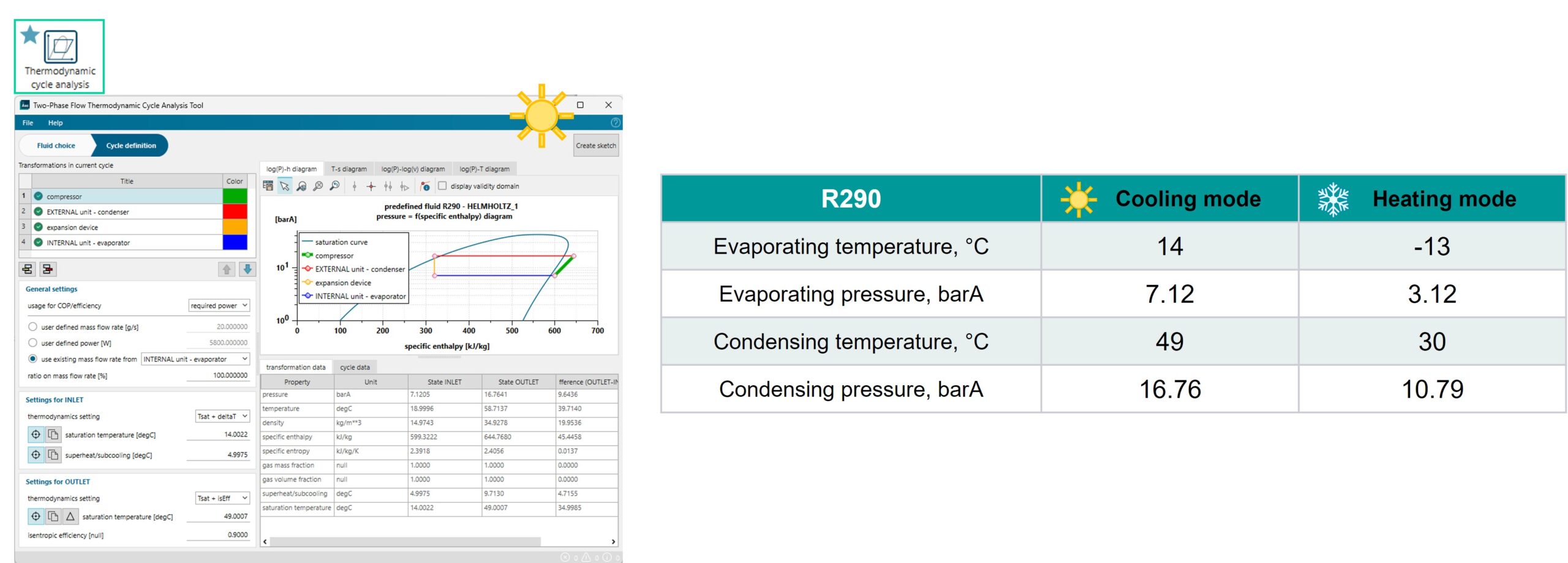
Engineers can quickly evaluate the impact of the refrigerant choice on the heat pump, by using the same thermodynamic cycle with the different refrigerants available within the standard Simcenter Amesim database.
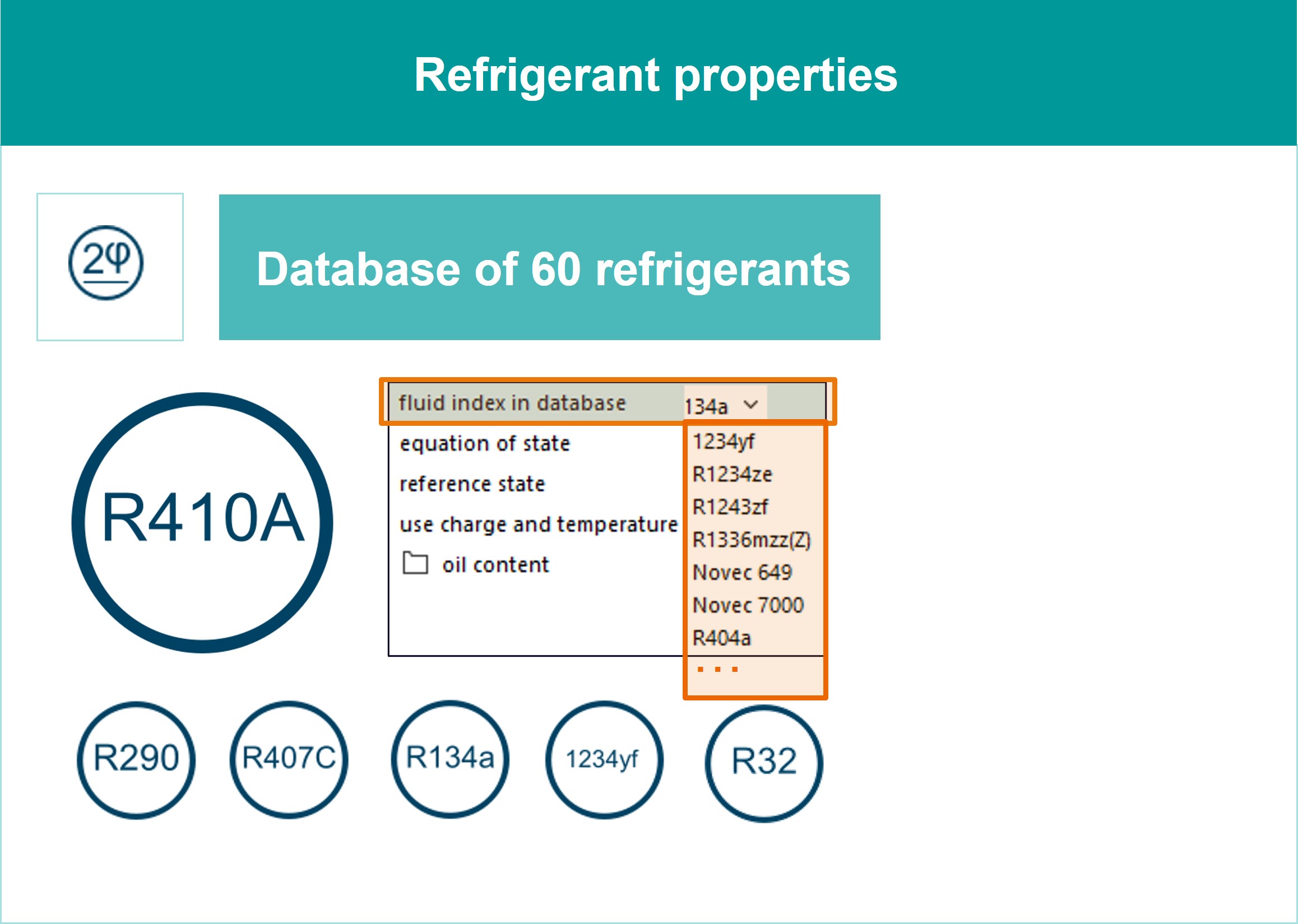
Figure 4 – Heat pump thermodynamic cycle with different refrigerants, in cooling mode
Propane R290 has multiple advantages since it is an environmentally friendly natural refrigerant with a GWP value at 3, it gives the highest COP due to its wide saturation curve, and it leads to the lowest discharge temperature and pressure levels. Though propane is a flammable refrigerant (A3) therefore equipment with a certain refrigerant charge requires safety measures such as ventilation and fire suppression systems.
Sizing Individual Components
After the definition of the thermodynamic cycles with its refrigerant, engineers can start designing the individual components able to realize them.
Heat Exchangers
From the building thermal model, the highest heat power demand is reached in cooling mode (summertime); consequently, the heat pump components are sized for the cooling operating mode. While in heating mode, the heat exchangers will be overperforming with the sizing coming from the highest cooling demand; consequently, the thermodynamic cycle in heating mode is optimized to satisfy the requirements but with a smaller temperature difference between the refrigerant and the air as well as lower fan speeds thus reducing the noise levels.
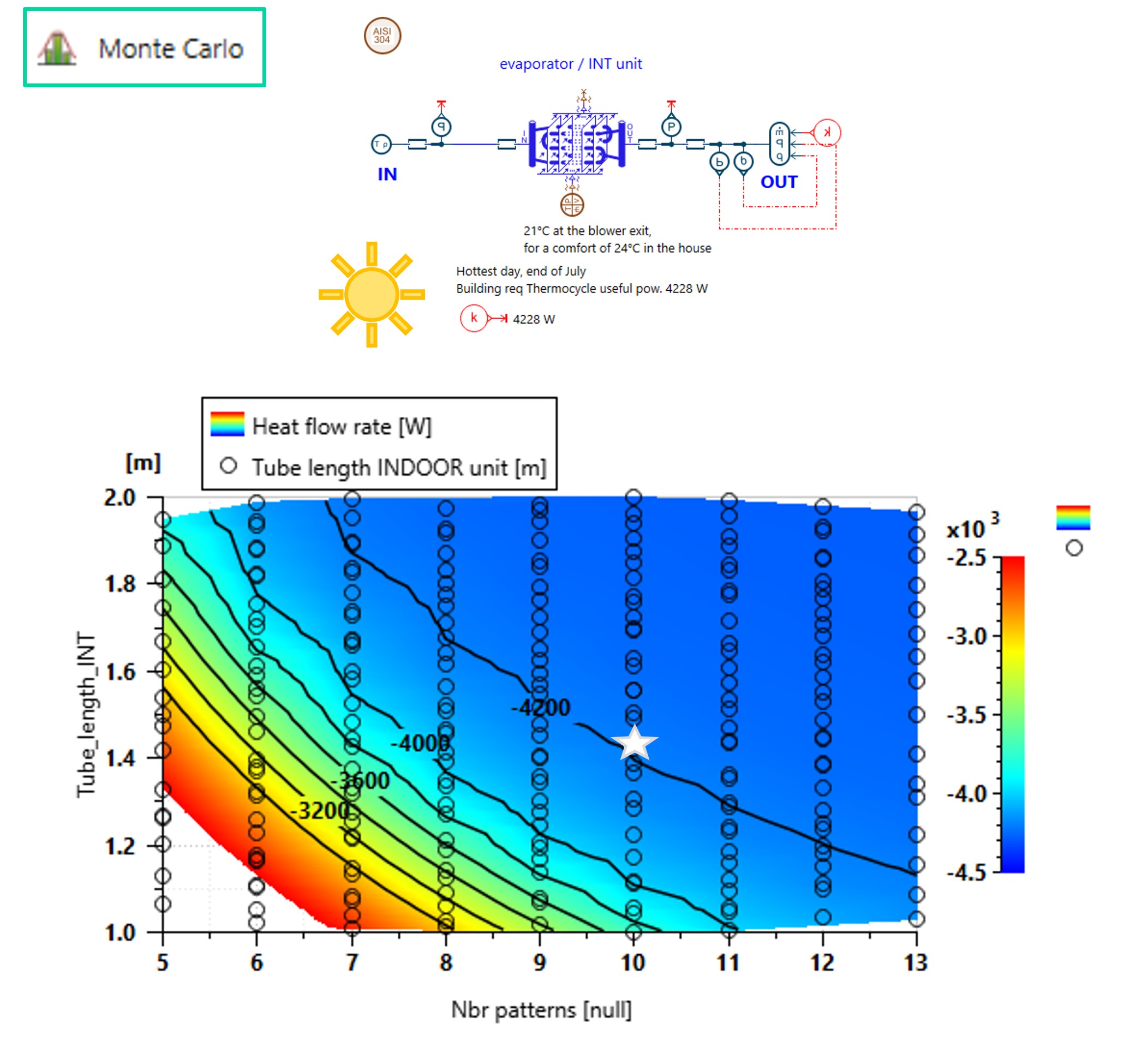
For the indoor and outdoor units, we consider fin-and-tube heat exchangers with a similar design based on a repeating pattern of six tubes per bank and three banks of tubes, as in Figure 5.

For sake of simplicity in this blog, the tube length (heat exchanger width) and the number of repeating patterns (consistent with the heat exchanger height) are chosen as design parameters to be sized for both indoor and outdoor units though other parameters could also be considered.
For the heat exchangers’ sizing, boundary conditions as from the thermodynamic cycle APP with R290 refrigerant as well as extreme external temperatures are applied to the component. A design space is explored using an Optimized Latin Hypercube sampling in a Monte Carlo study, whose simulation results are depicted in Figure 6. For the internal unit operating in cooling mode, it is found that 10 repeating patterns and a tube length of 1.45 m are suitable to meet the required evaporating power.
A similar study can be applied to the external unit as well to determine the design parameters to meet the required condensing power from the thermodynamic cycle APP.
In heating mode, the previously sized indoor and outdoor units will be overperforming compared to the required power. Consequently, the heat pump thermodynamic balance will be different from the expectations when working in closed loop. To avoid it, both the evaporating and condensing temperatures in heating mode are optimized for each unit to provide exactly the required evaporating and condensing heat powers. The process to optimize the heating thermodynamic cycle keeping the sizing of the units from the cooling mode is described in Figure 7.
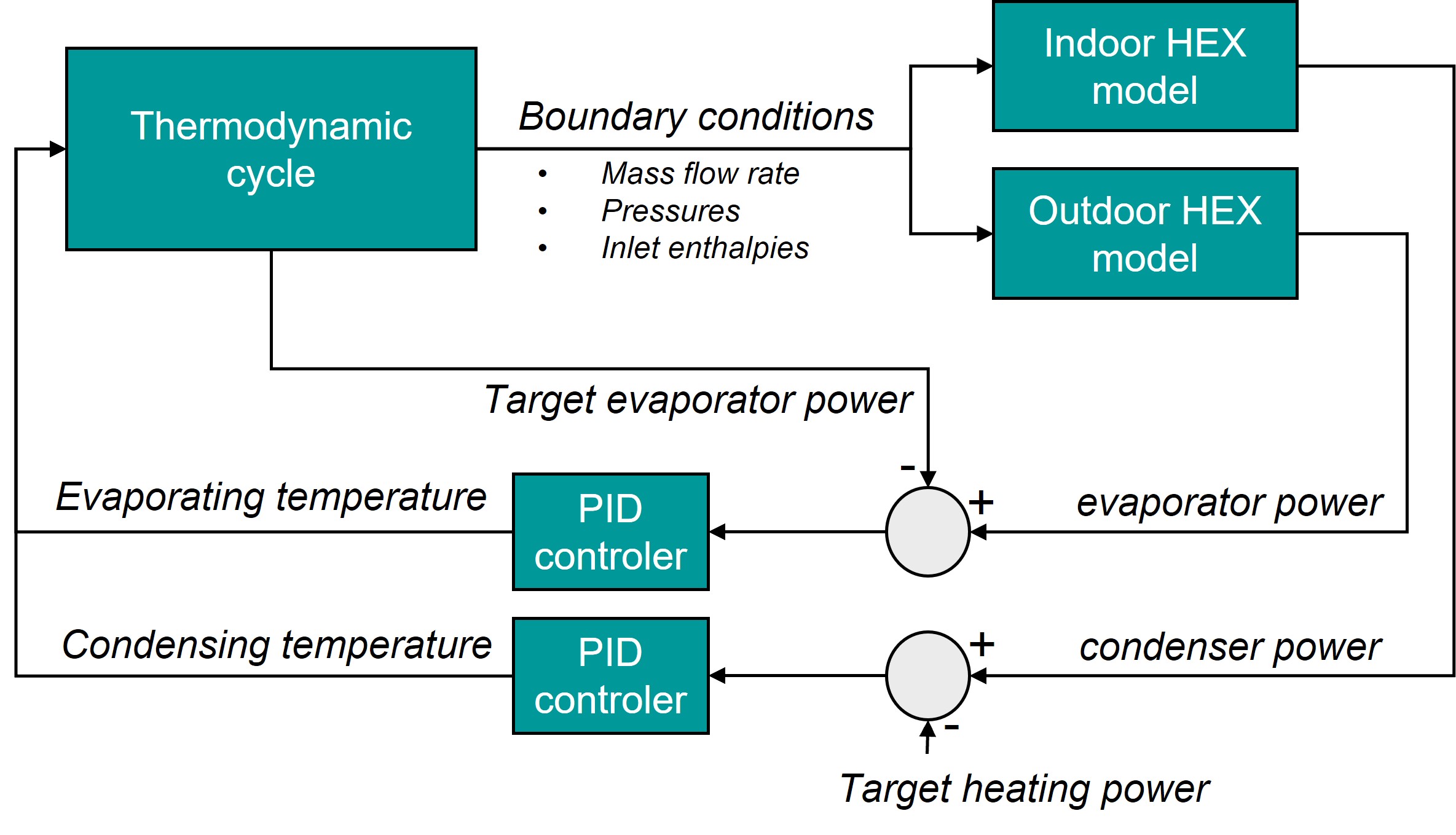
Figure 8 shows the resulting optimized cycle for the heating mode.

Compressor
The compressor is sized to deliver the maximum mass flowrate that in this blog corresponds to the cooling mode, with highest external temperatures.
Consequently, the displacement of the volumetric machine is computed by applying the boundary conditions from Thermodynamic cycle APP and the maximum speed (2500 rpm) such as to deliver the required mass flowrate for the cooling demand.
Depending on the availability on supplier’s catalogues, the compressor might have a different displacement than the ideal value; consequently, the rotational speed should be adapted to achieve the target mass flowrate.
Moreover, in heating mode the compressor speed should also be reduced due to the lower mass flowrate required for warming.
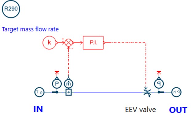
Electronic expansion device
The electronic expansion valve (EEV) is represented as an orifice with a singular pressure drop coefficient. The first obejective is to determine the size of the valve such as to provide the expected pressure drop with the require mass flowrate as from the target thermodynamic cycle.
In the closed loop heat pump, the EEV valve is controlled to keep the target evaporator outlet conditions.
Finally, assembling all the previously sized components along with piping and the 4-way valve (reversing flow valve), an open loop model (open at compressor suction point with pressure and enthalpy boundary conditions) can be used to determine the necessary refrigerant charge in the rest of the system (active charge) for both heating and cooling mode.
An accumulator will be added in the system to be able to properly store the difference of charge between the two modes such to be operational in both heating and cooling.
Validating the closed loop system
The closed loop system model is obtained by replacing the reference suction boundary conditions with the accumulator and imposing to the system the refrigerant charge previously calculated (the highest value between cooling and heating mode). Moreover, a PID controller for the EEV valve is introduced to ensure that the evaporator outlet conditions and a 4-way reversing flow valve is added to switch the heat pump’s operating mode.
The reversing flow valve is easily represented using the Valve Builder, a Simcenter Amesim tool that automatically creates valves’ functional simulation models from an interactive GUI where all port connections can be easily drawn and parametrized.
Finally, heat exchanges can occur internally to the reversing flow valve between the hot and the cold line as represented in Figure 10. These are additional contributions to the evaporating and condensing powers, and they can be considered as well in the final heat pump simulation model in Figure 12.
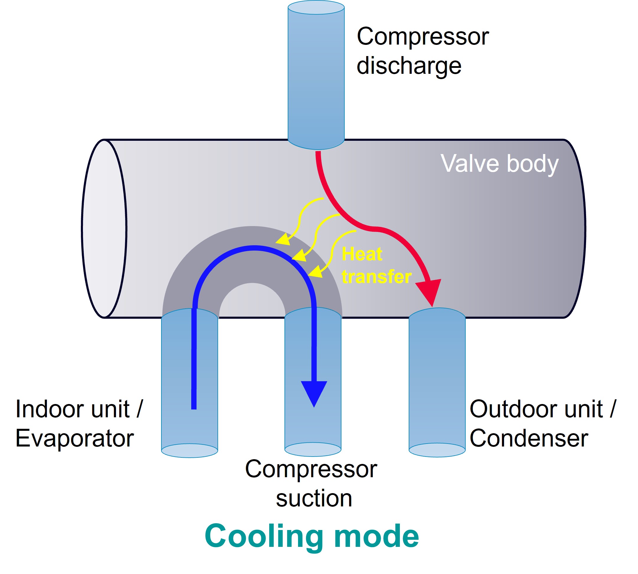

Figure 11 – Two-zones thermal model of the residential building and simulation results
Engineers can verify that the reversible heat pump is meeting the steady-state cooling and heating requirements for the residential building during the hottest and coldest days of the year; anyway, the system is expected to work in various external conditions and loads during its long operational life.
The simulation model can be then leveraged to verify the heat pump performance, exploring the variation of parameters and their impact on meaningful KPIs.
In this blog we perform a Monte Carlo study using an optimized latin hypercube sampling for the compressor speed and the external air temperature.
It is interesting to highlight that the reversible heat pump can satisfy high cooling power demands with very good coefficient of performances even with very hot external conditions. Similar conclusions in heating operation.
Virtually integrated building simulation with Simcenter Amesim
The heat pump previously validated in steady state conditions can be virtually integrated in the building simulation model to verify the interactions and the dynamic response to external and internal loads during several hours or even days of operation, as in Figure 14.
The building thermal management model includes all control logics regulating various components:
- Compressor: a PID controller is controlling the angular speed based on the actual and target house temperatures
- Fans: a PID controller is regulating the air velocity based on the actual and target house temperatures
- Mixing Air: a certain percentage of external fresh air is mixed with recirculating air to guarantee the right indoor air quality, without penalizing the energy consumption of the HVAC system. The external air changes are regulated by a PID controller based on the house’s current and target temperatures as well as the ambient temperature
- Electronic expansion valve (EEV): a PID controller is regulating the valve opening to keep the target evaporator outlet enthalpy
The fully integrated building thermal management model can be leveraged to verify the right sizing of the heat pump in dynamic conditions without over-engineering. Moreover, control strategies can be optimized considering variable external and internal loads as well as working modes.
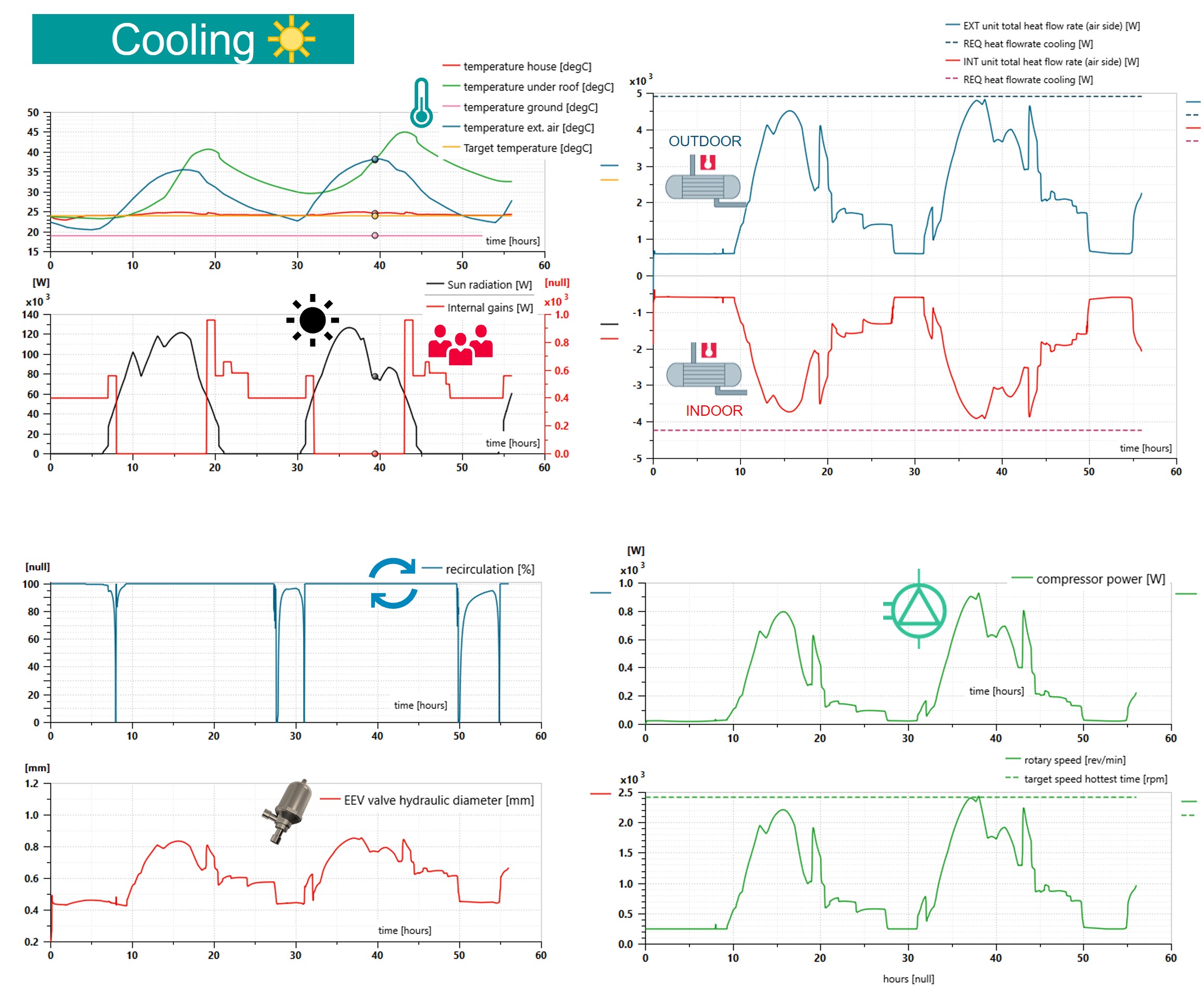
In summertime the integrated simulation model highlights that the heat pump is properly keeping the target temperature within the house, with strong sun radiation and occupants’ activities, over multiple days with good COPs also in the hottest hours.
Figure 14 shows some meaningful simulation results:
- Time histories of temperatures in the two zones of the house as well the external conditions and the target value
- Percentage of recirculated air
- Opening of the EEV valve
- Condensing and evaporating powers with respect to the initial building requirements estimation with the hottest external temperature
- Compressor power and speed
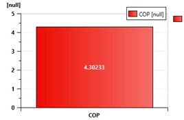
- Good COP of the heat pump, also with an ambient temperature reaching 38.3 °C at 4 p.m on the second day
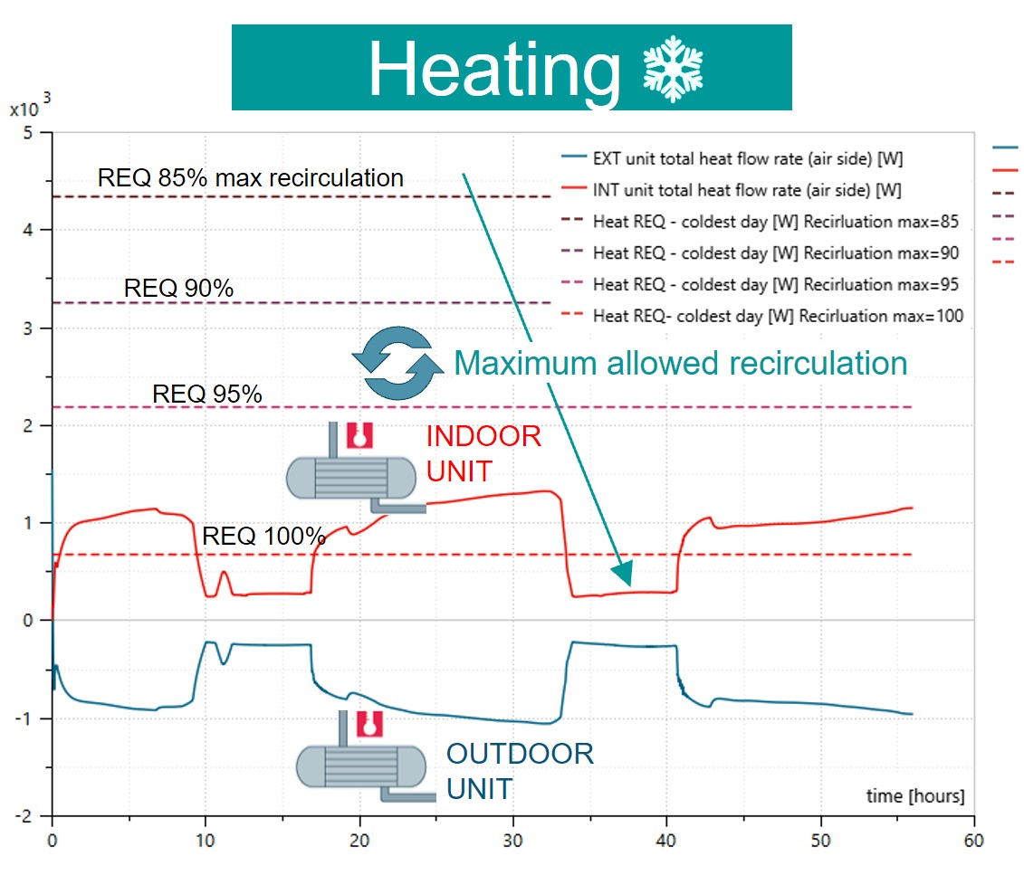
In wintertime the integrated simulation model shows that well-insulated buildings with strong sun radiation and good exposition can reach indoor temperatures above the target values in the afternoon hours. The air ventilation system plays a critical role in terms of air quality but also heat exchangers sizing and operation, as well as energy consumption of the system.
Conclusions
Simcenter Amesim offers HVAC engineers a comprehensive simulation workflow and an extensive set of tools to design, analyze, and optimize reversible heat pumps using low-GWP refrigerants. It enables engineers to assess system performance, improve energy efficiency, and virtually benchmark emerging technologies, accelerating innovation while contributing to a more sustainable future.
Want to learn more?
- On-demand webinar: How Daikin Malaysia is using simulation tools to improve comfort and sustainability of HVAC systems
- On-demand webinar: Unlocking HVAC system models ROI through democratization
- On-demand webinar: Improve energy efficiency and performance of next generation cooling and heating technologies through digitalization
- Read this paper: Leveraging System Simulation to Support the Design of a Reversible Heat Pump