Bearing Transmission Failures: How to Avoid Them With Virtual Prototyping
Improving bearing design with virtual prototyping to help limit downtime and avoid failures
Bearings allow complex machinery to rotate by making the rotation possible and reducing the friction. Still, a significant part of the friction that occurs, happens inside the bearings. Depending on the load conditions, bearings tend to wear, and the temperature will rise. This makes bearings key components for both system efficiency and reliability. For example, in wind turbines, most of the mechanical failures that occur (measured in shutdown time) are due to the bearings [1]. Quantitatively, operation and maintenance costs represent 20-30% of the lifecycle cost onshore, and up to 30% on offshore installations. Cracks can occur in bearings with less than 3 years operation, which only represents 5-10% of the expected lifetime of a bearing. Can we avoid bearing failure with virtual prototyping?
Bearings are clearly important for the operations and the reliability of mechanical products. Therefore, manufacturers invest to make the bearings better. Doing that based on tests is quite expensive, and also difficult, since you cannot realistically put a sensor inside a bearing to perform direct measurements. It is possible to use condition monitoring to interpret experimental signals and detect a bearing failure when it happens.
Virtually Design the Bearings
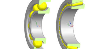
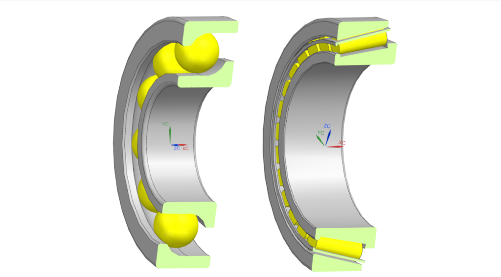
Therefore, a simulation-based approach is a more attractive alternative. You can use virtual prototyping tools to virtually design the bearings, evaluate the performance (dynamics, noise, durability) and optimize the design. This makes the design cycle shorter, and improves the bearings to ensure less failures in its lifetime. In Figure 1, there are some bearing examples.
Gears and bearings are positioned differently in the market. There are many gear vendors, and gear models are available in a range of commercial software tools. Bearings only have a few manufacturers, who also sell bearing analysis tools to product manufacturers who wish to integrate the bearings in their products. Sometimes, product manufacturers only rely on analysis tools from bearing manufacturers, in which only the bearing model is available. This puts limitations on the engineering process. The bearing models are not extended to a full drivetrain model with electromotor, as would be done in a multibody simulation package to evaluate and improve the product performance. In other cases, only stiffness matrices are available, which do not give insight in all relevant phenomena (for instance, the ball passing frequency cannot be predicted).
Advanced Bearing Modeling for Multibody Simulations
It is important to predict the detailed mechanical behavior of the bearings. The bearing models allow design engineers to optimize the design based on simulations, before it’s manufactured. With accurate load predictions onto the structure and insight in the internal force distributions within the bearing, this is achievable now. With an advanced multibody simulation approach, design engineers can accurately predict a bearing’s performance, evaluate alternatives and optimize the design.
Simcenter 3D is a unified, scalable, open and extensible environment for 3D CAE with connections to design, 1D simulation, test, and data management. It can be used to predict the performance of your 3D geometry-based designs. Simcenter 3D supports a range of bearing models for multibody simulation (MBS). The standard bearing formulation is a 6×6 stiffness and damping matrix. The analytical bearing formulation offers various ball bearings (Deep Groove Ball Bearing, Angular Contact Ball Bearing, Thrust Ball Bearing) and roller bearings (Cylindrical Roller Bearing, Tapered Roller Bearing).
Simcenter 3D Motion Transmission Builder
A previous blogpost has introduced the Simcenter 3D Motion Transmission Builder for rapid design engineering of gear boxes, the other important component in modern powertrains. It shows an example of a bearing forces frequency spectrum derived from run-up simulation for a two-stage transmission. The Transmission Builder can be combined with the bearings solution. For full system-level NVH, it is important to consider the correct load path from the shaft to the vibrating gearbox structure. This means that both the gear contacts and the bearings must be simulated with a high accuracy. Read this Siemens white paper for more information.
Using The Bearing Manager
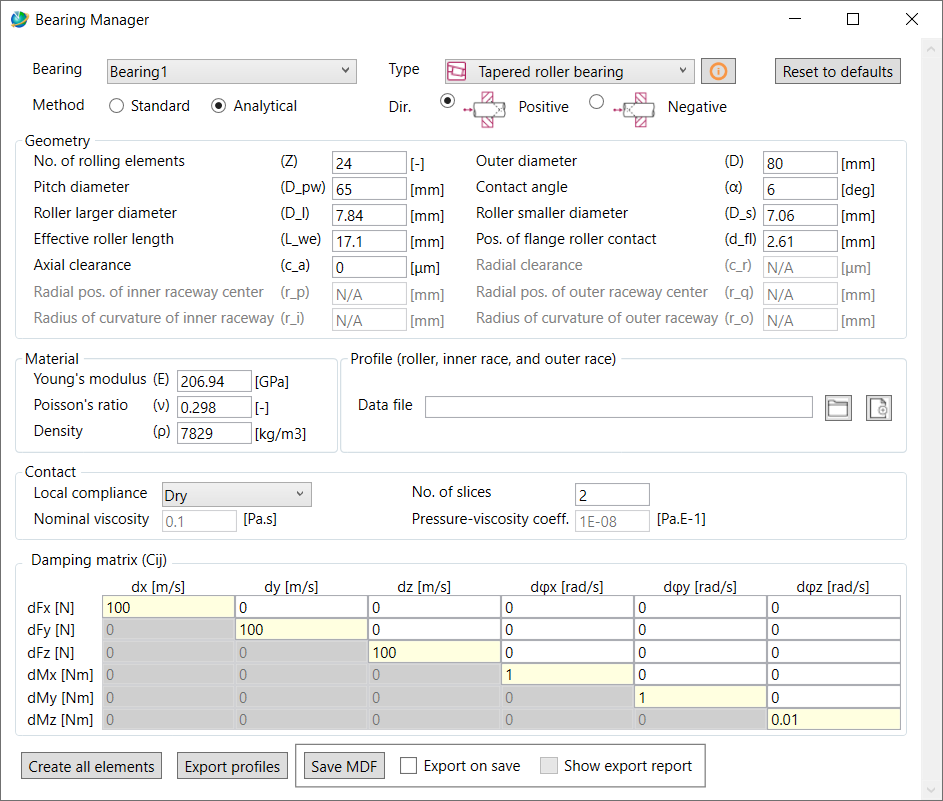
A new bearing interface solution is available with Simcenter 3D Motion. The Bearing Manager (see Figure 2) is used to define the bearing. You first select the bearing type. For your model, you can choose between standard (define 6×6 stiffness and damping matrix) and analytical (you can model the nonlinear behavior, parameterize the geometry, and define the roller crowning). Thereafter you can specify the geometry, define the materials, the contacts and the damping. Finally, you create the input for the Simcenter 3D Motion solver: you create the bearing models, for which the performance is subsequently computed.
The bearing element can be classified as a physics-based force element in Simcenter 3D Motion. In a nutshell, based on the inputs, the physics inside the bearings are solved, and one can compute the forces. This does not involve the use of look-up tables. If the internal geometry and the lubricant information are available, all the supported bearing models can be computed.
Effects of Lubrication
For the bearing element, the standard contact is a dry contact (with the Analytical method). However, bearings are often lubricated, which has a significant effect on the contact mechanics and rotational behavior of the bearings. To include the lubrication effect, you can switch to the Elastohydrodynamic Lubrication (EHL) formulation (see Wijnant [2] for point contact / ball bearings, and Wiegert et al. [3] for line contact / roller bearings). EHL means that the contact surfaces in the bearings have a significant elastic deformation, which changes the shape and thickness of the lubricant film in the contact.
In paper [4] a bearing element model is reported that corresponds to the analytical model with a dry contact model. This is compared with a CAD-based model, which is converted to an MBS model with joints, bodies and forces. This model is accurate and efficient, but more computationally demanding than the bearing element. It is more challenging to set up, as the user needs to tune several settings. The main settings are the cage (that holds the balls at correct distances) and the contact parameters. The cage is modeled with springs that should be stiff enough, but not too stiff. When comparing both models, the bearing element is between 5 and 15 times more efficient than the MBS model.
Results
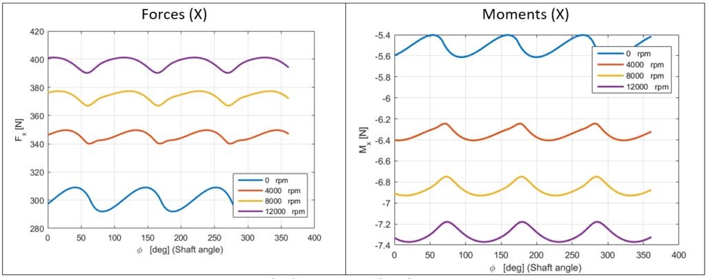
Let’s look at some example results for an angular contact ball bearing case, as shown in Figure 1. The EHL contact model is used. The inner ring is displaced with respect to the outer ring. Then the bearing is put in motion about its main axis and the reaction forces on the outer ring are observed for different velocities. A simulation is performed in which the displacement is fixed and the rotational speed is increasing. The forces and moments in the X-direction are shown in Figure 3. You can see two things:
- When increasing the velocity, more lubricant is dragged between the contacting surfaces, which results in a greater force exchanged between the rolling element and the raceways. The rolling element is being squeezed between the two raceways.
- There’s modulation due to rolling elements that change position (representing the ball passing frequency)
Model the Full Powertrain
Futhermore, with the Simcenter 3D portfolio enriched by its new bearings capability, you can accurately model the full powertrain and driveline, then evaluate the dynamics. On component level, the bearing simulation results give insight in the forces, moments and lubrication effect. This allows powertrain engineers to correctly define and design the bearings needed for their product.
On a system level, an accurate bearing model can help to correctly foresee e.g. the misalignment of the gear pairs. Misalignment in gears can potentially lead to rough functioning of the transmission with consequent high vibrations and inevitable degradation of the quality of the components, ultimately leading to failure.
Consequently, using an accurate bearing model with the already available capabilities of Simcenter 3D Motion will not only enable the design improvement of the component itself, but it will also boost the predictivity of the system model especially when there is a strong coupling between the different components.
Ongoing Research Towards Future Solutions
The new bearings solution has been achieved through in-house research and development efforts of the Simcenter 3D multibody team.
An important part of researching state-of-the-art technology and the creation of proof-of-concept toolsets for bearings is performed in the Baekeland PhD research project “Development and Validation of modelling techniques for lubricated contacts” [5] funded by VLAIO, which supports the PhD research of Leoluca Scurria. Industry partner is Siemens Industry Software NV (SISW), Academic promoter is Ghent University (Prof. Dieter Fauconnier and Prof. Patrick De Baets), and Academic research partner is KU Leuven LMSD (Prof. Wim Desmet).
Finally, the main step forward in this Baekeland PhD project is the research and development of methodologies for lubricated contacts, available for multibody simulation of full bearing models (whereas previously these contact methodologies were only applicable to single component models). This is a smart solution strategy: efficiently treat the full models with a model-order reduction (MOR) strategy. The new R&D solutions are candidates for future releases of Simcenter 3D Motion.
Acknowledgements
Part of this work has been performed in the frame of the Baekeland PhD project “Development and Validation of modelling techniques for lubricated contacts” (Ref. Nr. 160228) of Leoluca Scurria, 2016-2020, funded by VLAIO (Flemish government agency Flanders Innovation & Entrepreneurship).
References
[1] H.D. Machado de Azevedo, A.M. Araújo, N. Bouchonneau, “A review of wind turbine bearing condition monitoring: State of the art and challenges”, Renewable and Sustainable Energy Reviews, 56, pp. 368–379, 2016.
[2] Y.H. Wijnant, “Contact dynamics in the field of elastohydrodynamic lubrication”, PhD Thesis, University of Twente, Enschede, The Netherlands, 1998.
[3] B. Wiegert, H. Hetzler, W. Seemann, “A simplified elastohydrodynamic contact model capturing the nonlinear vibration behavior”, Tribology International, Vol. 59, pp. 79-89, 2013.
[4] L. Scurria, J. Cavalaglio Camargo Molano, P. Jiranek, T. Tamarozzi, D. Fauconnier, “Rolling Element Bearings – Advanced Modeling for Multibody Simulations”, 2020 SAE World Congress, April 21-23, 2020, Detroit, MI, USA.
[5] L. Scurria, “Development and Validation of modelling techniques for lubricated contacts”, VLAIO Baekeland PhD Mandate, Ref. Nr. 160228, 2016-2020.