Aero-engine sub-component design with the Mechanical Digital Twin
Challenges in Aero-engine engineering
Aero-engines are complex machinery, largely because they experience deformations, include moving parts, and are subject to forces as well as torques, flow and thermal effects. They contain devices which make its functions more stable, such as, variable stator vanes (VSVs) which can be reoriented while the engine is running, resulting in control of the flow angle, streamlining efficiency in a wider range of operating conditions.
One important challenge of engineering a machine like an aero-engine is fuel consumption reduction, which can be done with other devices such as variable bleed valves (VBVs) which allow the extraction of air or particles exited by the low-pressure compressor. Opening the VBV reduces fuel consumption by slowing the engine’s idle speed during descent phases.
For the design of an aero-engine, there’s a need for advanced simulation methodologies that can master its complexity and optimize performance. Each new engine must meet thousands of regulatory and contractual requirements. Consequently, engineering teams must solve complex design problems within a distributed supply chain, typically spread over multiple departments and supplier partners. These types of challenges necessitate the implementation of a full digital twin, so that test and simulation are an integrated part of the design process of the aero-engine.
The aforementioned actuated systems (VSV, VBV, …) require tools that allow simulation of the complete subsystem to reduce product weight with the use of complex materials like composites, to predict the deformation of key parts of the assembly under real working conditions, and finally to predict wear with an accurate contact algorithm.
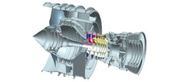
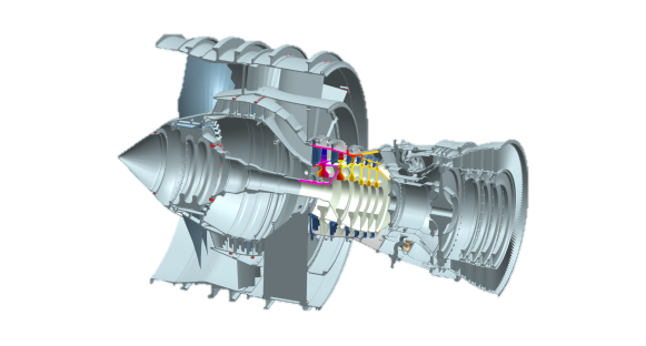
Engineered structures like the engine in Figure 1 experience nonlinear displacement because of deformations and kinematic motion. With the Simcenter Nastran Solution 402, Siemens Digital Industries Software now has a solution: robust algorithms which support large displacement and rotational behavior in combination with flexure. This is possible thanks to the introduction of kinematic joints in Simcenter Nastran SOL 402, along with adequate drivers and time constraints to control the realistic simulation of the complex machinery.
The involvement of Siemens in E-BREAK
E-BREAK (Engine BREAKthrough Components and Subsystems) was a large-scale integrated project, funded by the European Commission, which started in October 2012 and that lasted until the end of March 2017. For more information, see this link.
E-BREAK’s aim was to reduce air traffic emissions by adapting sub-systems to new constraints of temperature and pressure. This was possible through developing, validating and integrating specific key subsystem technologies required for the next generation of engines. E-BREAK has made targeted sub-systems breakthroughs through improvements regarding mass reduction, material resistance, sealing technologies, oil systems, abradable materials, tip clearance control, stability of the engine in off-design operations and health monitoring.
In E-BREAK, Siemens has acted as a sub-contractor of main European Aero-Engine OEMs to develop new solver capabilities related to the simulation of Variable Stator Vane (VSV). Those new features rely on the ability of the solver to accurately model complete sub-systems by considering Finite Element Analysis (FEA) models of the components connected by a set of flexible kinematical joints. Since the project, the results have become the basis for what is now the Simcenter Nastran SOL 402 solution.
Achieving the mechanical digital twin for an Aero-engine
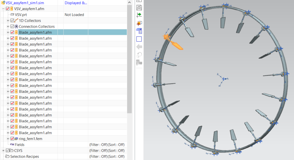
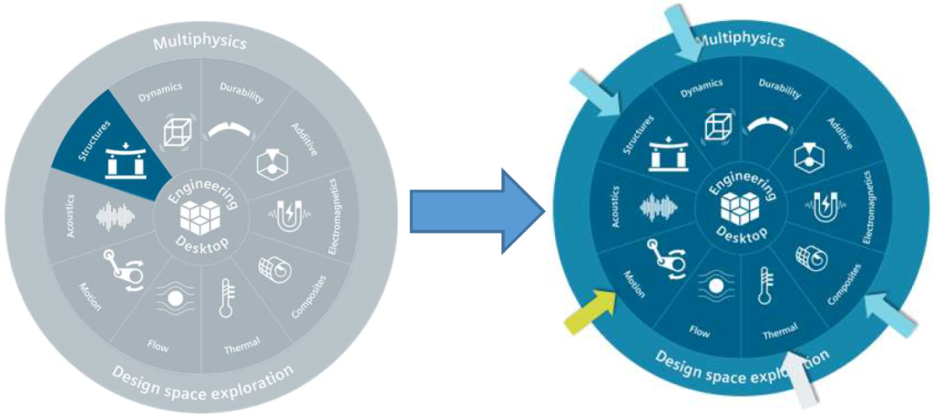
Simcenter 3D, the unified, scalable, open and extensible environment for multi-attribute CAE, helps to achieve a digital twin, while the support of the Assembly Finite Element Model (AFEM), based on assembly CAD (Computer-Aided Design), enhances workflows for analyzing complex assemblies.
The support of multi-disciplinary simulations is a key feature of Simcenter 3D, as it can provide realistic virtual simulation. It also offers, among other things, many structural analysis solutions that can be applied to several applications to simulate structural performance. Simcenter 3D makes it possible to combine multiple disciplines into a single analysis for aero-engine sub-components simulation.
More than a structural analysis
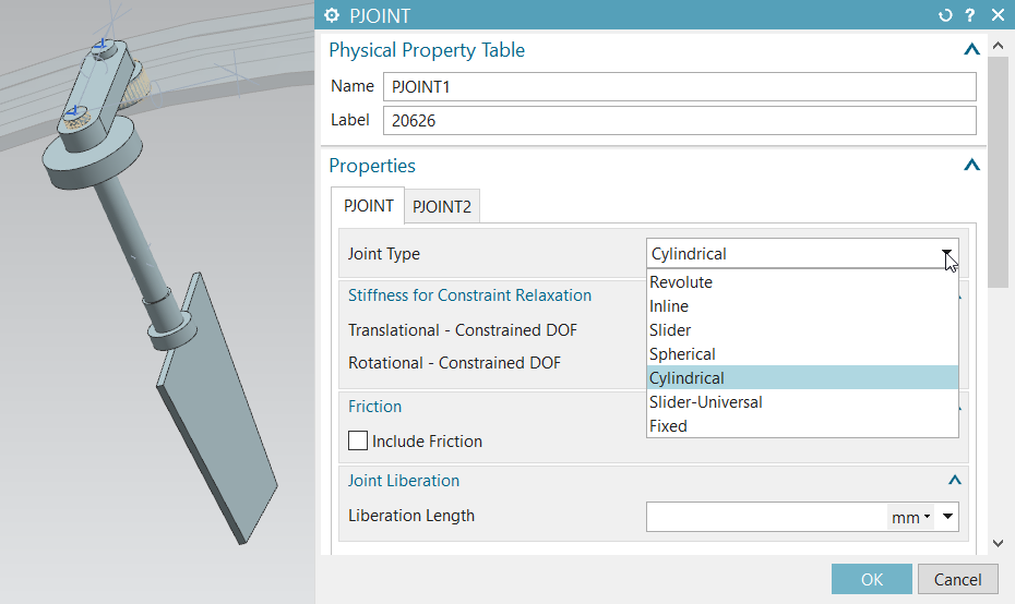
Simcenter Nastran SOL 402 supports structural dynamic analysis which deals with complex materials. It takes into account the effects of temperature variation and it can handle large assemblies with moving parts. Simcenter Nastran SOL 402 can handle large displacements and large rotations. The software features an extended library of rigid and flexible kinematic joints that can be included in Finite Element mesh(es).
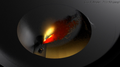
Furthermore, complete kinematics and dynamics of a system can be simulated through FEA. Nonlinear and fully meshed components can be included, capturing the complete material and geometrical nonlinear structural behavior. The VSV analysis example in the figure below exhibits stress concentration resulting from the ring’s rotation. This illustrates that, for an industrial case which involves kinematic elements with large displacements and rotations, Simcenter Nastran SOL 402 offers highly accurate Finite Element analysis results. Recently, Safran Aircraft Engines gave a presentation [1] about nonlinear FEA for aircraft engines mechanisms at the 2019 Simcenter Conference in Amsterdam, The Netherlands. The presentation includes the highlights of 15 years of industrial applications in this domain.
Reference:
[1] C. Paleczny, B. Cauville, D. Granville, “Aircraft Engines Mechanisms Non Linear FEA Multi-Level Modelling”, 2019 Simcenter Conference, December 2 – 4, 2019, Amsterdam, The Netherlands.