Are heat pipes any good for my CPU?

When researching improved heat sink design to cool a CPU in a model I am developing, a common theme I kept coming across was integrating heat pipes with a heat sink base. All of these looked pretty complicated to start with and looking deeper into the design, the thermodynamics of it got more intriguing.
I won’t go into too much detail on the theory of how a heat pipe works as there are many articles and textbooks that can do a much better job of this and I would be here all day.
The essentials are a hollow pipe is connected to a heat source where evaporation of the liquid inside, in our case water, causes the fluid to heat up, change to a vapour and move towards the cooler condenser end. Once it reaches the condenser the vapour cools down, changes to a liquid and begins to move back towards the evaporator end create a cycle. This is very effective at transferring the heat away from our critical component of the CPU, and works at room temperature as heat pipe is evacuated, so it contains no air, only vapour.
While all this is very good in theory, can this even be modelled for an electronics cooling simulation?
The answer is yes with Simcenter Flotherm XT and I needed to do some further research and importantly some calculations.
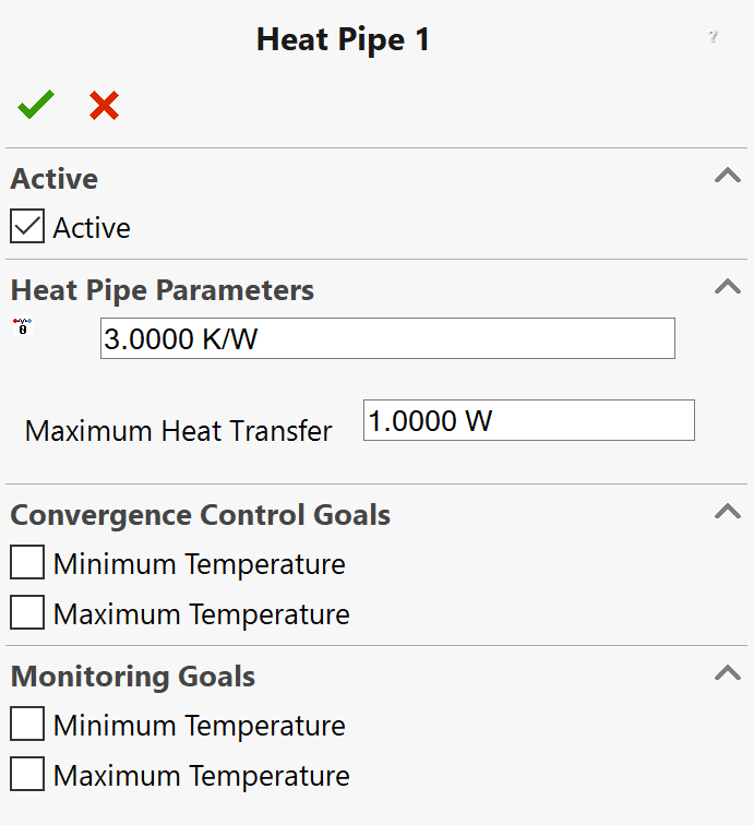
The Heat Pipe feature allows any pipe geometry to be modelled as a heat pipe. The two parameters given are the effective thermal resistance and maximum heat transfer. I was initially a bit stuck on where to find an appropriate value to use. After some research and consulting experienced colleagues, I found a way to first calculate the effective thermal resistance.

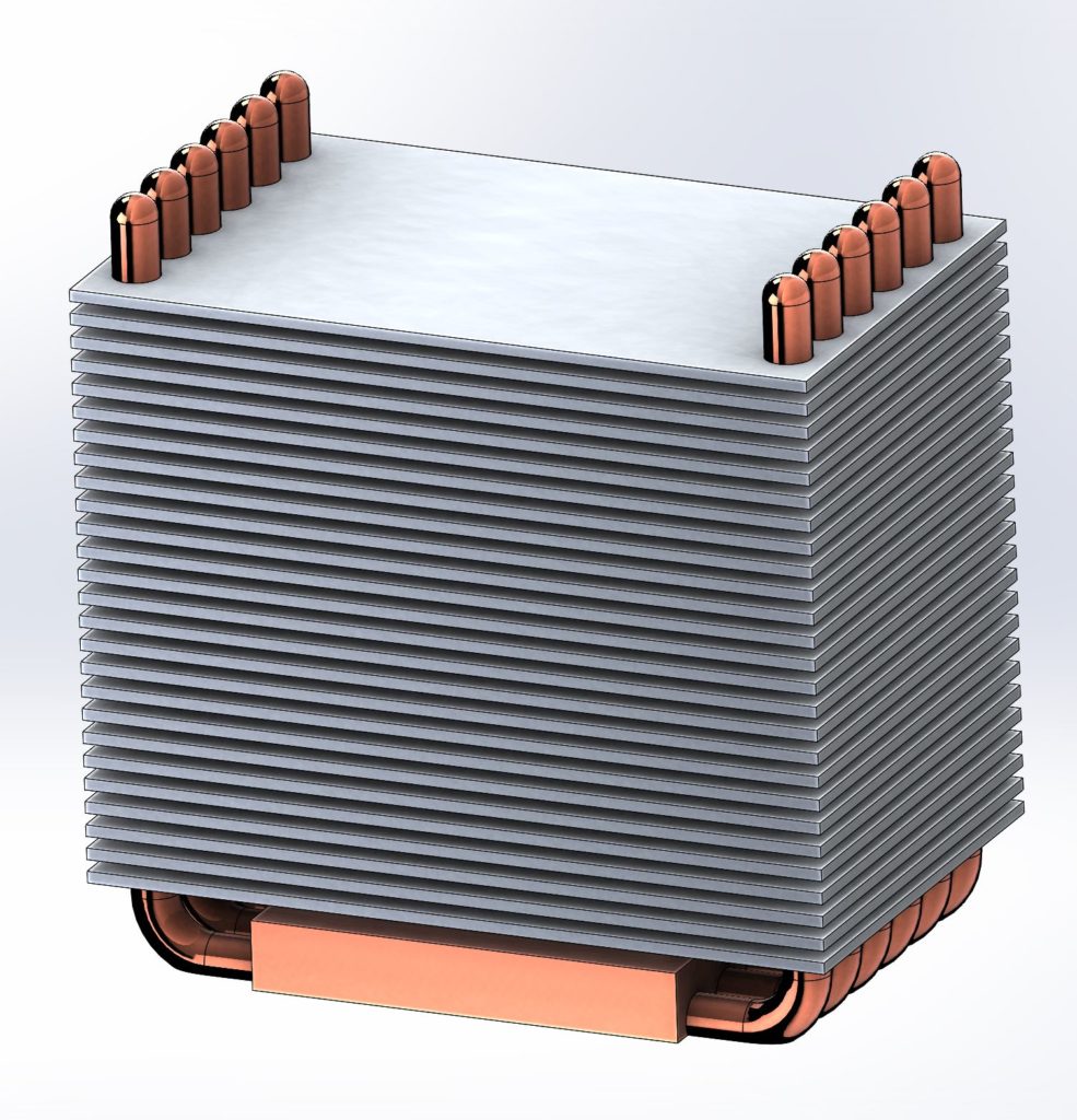
First I created the geometry of the copper heat pipes and block and the aluminium plates and then assembled then to create the heat sink. I created several iterations and I decided on this final design below that fit the surrounding enclosure.

I used the heat pipe calculator from Celsia Inc to determine the effective thermal conductivity by measuring the evaporator length and the condenser length based on the instructions on the website. With these values entered, I was given an effective thermal conductive table based on the pipe thickness used. I matched my 4mm diameter pipe to the value given under 4mm column and had a value to use.
From here I could calculate the effective thermal resistance using the formula
Reff = L / Keff A
L = Length of heat pipe
Keff = Effective thermal conductivity (given)
A = Cross sectional area of pipe
For the pipe I assumed the pipe thickness of 0.5mm and used that to calculated the cross sectional area.
The value for Reff was calculated as 0.86 K/W which was a reasonable estimate.
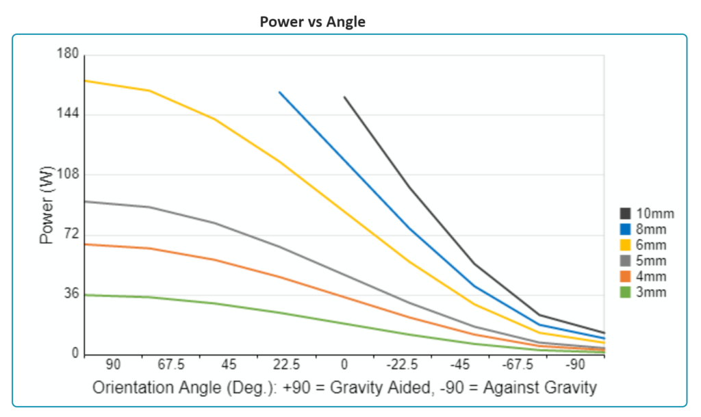
Once this was calculated, the maximum heat transfer was simply taken from a power against angle graph provided by Celsia. I tracked the 4mm pipe thickness line down to 0 degrees orientation as the heat sink is orientated in a way it is perpendicular to gravity effect so is neither aided or hindered by gravity. From this graph I got a value of 36W.

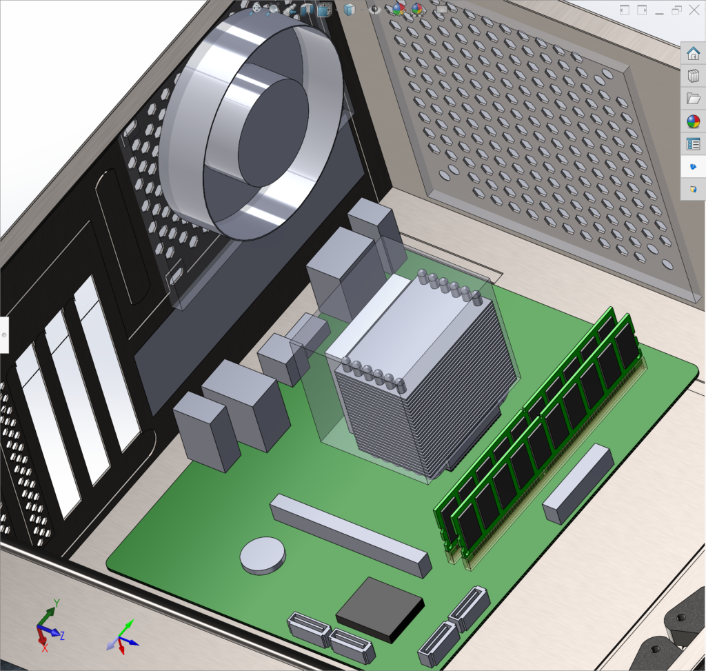
With all these value calculated I could replace the old heatsink setup with the new one and solve. After a first initial solve I decided to rotate the heat sink around its axis to help the air flow move through the heat sink and be extracted out towards the out take fan at the back of the CPU. This reduced the CPU temperature the most.

With this iteration, the final maximum temperature was 60.8° which was a reduction of 2.2 degrees from the original model which is a good improvement considering only the heat sink was changed.
This improvement in the real world would allow the CPU to run longer at a higher power without the risk of overheating or long term damage to the chip.
I learned a lot from the Celsia website and calculator on heat pipe physics and properties. Celsia use electronics cooling simulation to develop thermal management solutions for their clients. See a recent video online describing how they design custom heat sinks and integrate heat pipes with heat sinks into high end electronics designs using Simcenter Flotherm simulation tools.


Comments
Comments are closed.