Flexible spline curve control in the D-Cubed Dimensional Constraint Manager (DCM) – part 2
This post forms part two of the article which examines spline curve shaping functionality in the D-Cubed Dimensional Constraint Manager components (2D DCM and 3D DCM). You can find part one of the article here.
Introduction and recap
Part one of this article focused on the creation of flexible spline curves in a geometric constraint manager such as the DCM. The article discussed the questions that may be encountered when defining the shape of a spline curve using a set of user-defined points. The article also explored how adding spline interpolation conditions enabled additional constraints to be added between the spline and other geometry, without over-defining the spline curve.
Part two of this article focuses on the use of DCM variables for linking spline shape to other control geometry via interpolation conditions. The article also discusses the choice of curve parameterisation, which affects solved curve shape when reshaping flexible spline curves.
Controlling spline shape using variables
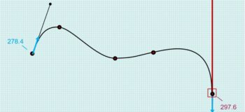
There are times when it is useful to add extra geometry to allow a user to control the shape of a spline curve. For example, consider Figure 1, where a linear segment might be added tangent to the left-hand side of the spline in order to control both the direction and magnitude of the tangent vector. The DCM works with unbounded geometries, so we will represent the linear segment using an infinite line passing through the left-most interpolation point, with a new point to determine the other end of the line segment (constrained coincident to the line).
The tangent direction of the spline curve can be controlled by adding an ordinary tangent constraint between the spline and the control geometry (line segment). As discussed in part one of this article, the internal freedoms of the spline will need to be increased by adding DERIV1 interpolation conditions to the left-hand end of the spline.
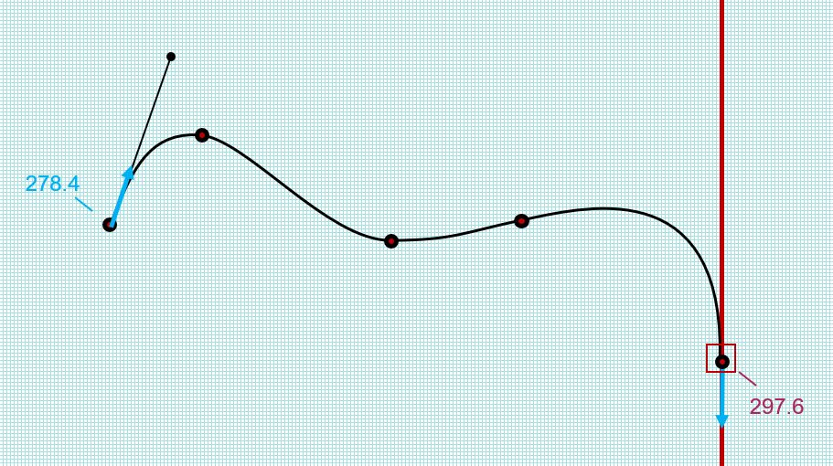
Figure 1: Adding a line segment to act as a control geometry
The magnitude of the tangent vector can be linked to the segment length using a DCM variable. The 2D DCM supports two types of variable – a variable dimension, which is associated with an existing dimension’s measured value, and a simple variable, which is a free variable and is not associated with any geometry positions by default. After a simple variable is created, it can be linked to the value of an interpolation condition. This is achieved by specifying the variable (v_node) as part of the spline data structure that is passed to the DCM whenever a spline is added or modified.
To connect the length of the line segment with the variable value, a separate variable distance dimension which measures the length of the segment will be added. The value of the variable dimension will be linked to the simple variable by adding a linear equation to the DCM.
Table 1 shows the set of interpolation conditions that are passed to the DCM when creating the spline curve. The simple variable vnVar1 is specified in the interp_v_nodes array for the first DERIV1_LEN condition. When assigning a variable to an interpolation condition, it is necessary to use a duration of IDURATION_CREATION_ONLY for the condition. This ensures that the corresponding internal spline freedom will not be fixed – it will be associated with the value of the variable, which remains a freedom until it is constrained by an equation. The numerical value provided by the application in the interp_vectors array will determine the initial value of the condition before the DCM attempts to satisfy the constraints during an evaluation.
| interp_ parameters | interp_ types | interp_ vectors | interp_ g_nodes | interp_ v_nodes | interp_ durations |
| 0 | DERIV1_DIR | 11.4, 32.9 | NULL | NULL, NULL | CREATION_ONLY |
| 0 | DERIV1_LEN | 278.4, 0 | NULL | vnVar1, NULL | CREATION_ONLY |
| 0 | G_COI | -2, -2 | Point1 | NULL, NULL | ALWAYS |
| 0.176 | G_COI | -2, -2 | Point2 | NULL, NULL | ALWAYS |
| 0.4797 | G_COI | -2, -2 | Point3 | NULL, NULL | ALWAYS |
| 0.6613 | G_COI | -2, -2 | Point4 | NULL, NULL | ALWAYS |
| 1 | G_COI | -2, -2 | Point5 | NULL, NULL | ALWAYS |
| 1 | DERIV1_DIR | 10.3, -35.7 | NULL | NULL, NULL | CREATION_ONLY |
| 1 | DERIV1_LEN | 297.6, 0 | NULL | NULL, NULL | ALWAYS |
Table 1: The set of interpolation conditions for the spline, as specified to DCM
g_nodes or vectors?
When using vectors to specify interpolation conditions, the use of IDURATION_ALWAYS can be restrictive, since use of this setting will result in no movement of the interpolation point, effectively preventing rigid transformations of the spline. However, for interpolation positions, adding the positions to the DCM as points overcomes this restriction and it is typical to specify IDURATION_ALWAYS, as in the table above. The points may then be fixed, as in this example, or may be left under-defined allowing rigid transformations of the spline in addition to spline reshaping (for flexible splines). In the latter case, the creation of extra interpolation conditions to increase spline freedoms may also be useful, since it facilitates spline reshaping without forcing the DCM to move the interpolation points.
For directional conditions such as first derivative conditions, there is no analogous condition type to reference DCM geometry, so vectors must be used. If preserving rigid transformational freedoms is necessary then a DCM constraint with a help parameter, such as a tangent constraint, should be used rather than a spline condition.
Choice of parameterisation
When specifying interpolation conditions on a spline, the choice of parameterisation method for the spline curve is an important consideration. For each condition specified, the chosen parameter value influences the shape of the spline solution. For example, in Figure 2 below, the effect on spline shape of varying an interpolation parameter value can be clearly seen.
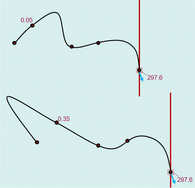
Figure 2: Comparison of spline shape for differing interpolation parameter values
It may be necessary for an application to update the parameter value for an interpolation condition, if the position of the condition has moved since the spline was created. The new parameter value is calculated using a curve parameterisation method, such as chord length or centripetal parameterisation. The 2D DCM supports curve re-parameterisation, allowing an application to implement its preferred parameterisation method. The 2D DCM also provides its own internal implementation of the chord length and centripetal parameterisations – for integrators working with this parameterisation, the DCM’s internal method should be used, to benefit from improved performance. Note that curve re-parameterisation is only supported for splines with interpolation point dependence.
The following example application code extends the code provided in part one of this article. It demonstrates the creation of a line segment with variable distance dimension linked to first derivative conditions on the spline end using a DCM variable:
// Example code showing the creation of a user-controllable interpolating spline
	// passing through a given set of interpolation positions.

	// The following code excerpt assumes that the calling application has
	// implemented and registered a set of DCM Frustum functions to provide
	// the necessary geometric data to the DCM
	// See the 2D DCM ex2 example program for an example Frustum implementation

	const int np = 5;				// Number of interpolating G_COI conditions defining the spline
	const int degree = 3;
	const int n_interps = np + 4;	// Total number of interpolation conditions (including DERIV1 end conditions)
	const double t_lower = 0;
	const double t_upper = 1;
	const double LIN_RES = 1e-8;
	const double ANG_RES = 1e-11;

	point*  anp[np];
	g_node* gnp[np];
	double g_coi_params[np];
	g_node* gninterps[n_interps];
	double params[n_interps];
	DCM_bs_itype itypes[n_interps];
	DCM_bs_iduration idurations[n_interps];
	v_node* vninterps[(n_interps) * 2];	// v_node array for linking DCM variables to interpolation conditions
	double vectors[(n_interps) * 2];
	unsigned int interp_index = 0;

	dimension_system* dsp;
	dsp = new dimension_system(LIN_RES, LIN_RES / ANG_RES);

	// Create the defining points for the bounded spline
	// These will be added as g_nodes to DCM later on
	anp[0] = new point(-62.3, 31.8);
	anp[1] = new point(-44.4, 49.6);
	anp[2] = new point(-6.2, 28.7);
	anp[3] = new point(19.5, 32.9);
	anp[4] = new point(59.4, 5.2);
	g_coi_params[0] = t_lower;
	g_coi_params[1] = t_lower + 0.176*(t_upper - t_lower);
	g_coi_params[2] = t_lower + 0.4797*(t_upper - t_lower);
	g_coi_params[3] = t_lower + 0.6613*(t_upper - t_lower);
	g_coi_params[4] = t_upper;

	for (int ii = 0; ii<np; ii++)
		{
		gnp[ii] = dsp->add_g(anp[ii]);
		dsp->fix(gnp[ii]);
		}

	// Set the DERIV1 conditions on the left-hand end of the spline
	params[interp_index] = t_lower;
	itypes[interp_index] = DCM_BS_ITYPE_DERIV1_DIR;
	idurations[interp_index] = DCM_BS_IDURATION_CREATION_ONLY;
	vectors[2*interp_index] = 11.4;
	vectors[2*interp_index + 1] = 32.9;
	gninterps[interp_index] = NULL;
	vninterps[2*interp_index] = NULL;
	vninterps[2*interp_index + 1] = NULL;
	interp_index++;

	params[interp_index] = t_lower;
	itypes[interp_index] = DCM_BS_ITYPE_DERIV1_LEN;
	idurations[interp_index] = DCM_BS_IDURATION_CREATION_ONLY;
	vectors[2*interp_index] = 278.4/(t_upper-t_lower); // Scale DERIV1_LEN condition based on parameter range
	vectors[2*interp_index + 1] = 0.0;
	gninterps[interp_index] = NULL;
	vninterps[2*interp_index] = NULL;
	vninterps[2*interp_index + 1] = NULL;
	interp_index++;

	// Set the G_COI conditions
	for(int ii = 0; ii<np; ii++)
		{
		gninterps[interp_index] = gnp[ii];
		params[interp_index] = g_coi_params[ii];
		itypes[interp_index] = DCM_BS_ITYPE_G_COI;
		idurations[interp_index] = DCM_BS_IDURATION_ALWAYS;

		vectors[2*interp_index] = -2;
		vectors[2*interp_index + 1] = -2;
		vninterps[2*interp_index] = NULL;
		vninterps[2*interp_index + 1] = NULL;
		interp_index++;
		}

	// Set the DERIV1 conditions on the right-hand end of the spline
	params[interp_index] = t_upper;
	itypes[interp_index] = DCM_BS_ITYPE_DERIV1_DIR;
	idurations[interp_index] = DCM_BS_IDURATION_CREATION_ONLY;
	vectors[2*interp_index] = 10.3;
	vectors[2*interp_index + 1] = -35.7;
	gninterps[interp_index] = NULL;
	vninterps[2*interp_index] = NULL;
	vninterps[2*interp_index + 1] = NULL;
	interp_index++;

	params[interp_index] = t_upper;
	itypes[interp_index] = DCM_BS_ITYPE_DERIV1_LEN;
	idurations[interp_index] = DCM_BS_IDURATION_ALWAYS;
	vectors[2*interp_index] = 297.6/(t_upper - t_lower);
	vectors[2*interp_index + 1] = 0.0;
	gninterps[interp_index] = NULL;
	vninterps[2*interp_index] = NULL;
	vninterps[2*interp_index + 1] = NULL;
	interp_index++;

	// Create a fixed vertical line - later we will constrain this to be tangent to the right-hand end of the spline
	EX_vec_2d dir1(0, 1);
	line line1(anp[np-1]->value(), dir1);
	g_node* gnLine1 = dsp->add_g(&line1);
	dsp->fix(gnLine1);

	// Create a line segment to use as a control geometry for the left-hand end of the spline
	EX_vec_2d dir2(10.91, 32.94);
	line line2(anp[0]->value(), dir2);
	g_node* gnLine2 = dsp->add_g(&line2);

	// Create end-point for line segment
	point ptSegment(-51.39, 64.74);
	g_node* gnPtSegment = dsp->add_g(&ptSegment);

	// Constrain end-points coincident to the line
	dimension coiSegment1(DCM_COINCIDENT);
	d_node* dnCoiSegment1 = dsp->add_d(&coiSegment1, gnLine2, gnp[0]);
	dimension coiSegment2(DCM_COINCIDENT);
	d_node* dnCoiSegment2 = dsp->add_d(&coiSegment2, gnLine2, gnPtSegment);

	// Create a simple variable that will be linked to the first DERIV1_LEN condition
	variable av1(34.7);
	v_node* vnVar1 = dsp->add_v(&av1);

	// Create a variable distance dimension to measure the line segment length
	dimension dist1(DCM_DISTANCE, 34.7);
	d_node* dnDist1 = dsp->add_d(&dist1, gnp[0], gnPtSegment);

	variable av2(34.7);
	v_node* vnVar2 = dsp->add_v(&av2, dnDist1);

	// Set the simple variable in the interp_v_nodes array
	vninterps[2] = vnVar1;

	// Create a linear equation which equates the simple variable with the variable distance
	linear_equation linearEq1;

	// Add the equation to DCM
	e_node* enLinearEq1 = dsp->add_e(&linearEq1, 0.0);

	// Add variables and coefficients to the linear equation (var1 - 10*var2 = 0)
	dsp->add_v_to_e(1, enLinearEq1, vnVar1);
	dsp->add_v_to_e(-10, enLinearEq1, vnVar2);

	// Make the spline
	spline sp(np, gnp);

	// Initial DCM_bs_data
	DCM_bs_data spdata;
	spdata.data_mask = DCM_BS_RIGIDITY | DCM_BS_PERIODICITY |
		DCM_BS_RATIONALITY | DCM_BS_DEPENDENCE |
		DCM_BS_PARAMETERISATION | DCM_BS_DEGREE |
		DCM_BS_INTERP_N | DCM_BS_INTERP_G_NODES |
		DCM_BS_INTERP_PARAMETERS | DCM_BS_INTERP_TYPES |
		DCM_BS_INTERP_VECTORS | DCM_BS_INTERP_DURATIONS |
		DCM_BS_INTERP_V_NODES;

	spdata.rigidity = DCM_BS_RIGIDITY_FLEXIBLE;
	spdata.periodicity = DCM_BS_PERIODICITY_NON_PER;
	spdata.rationality = DCM_BS_RATIONALITY_NON_RAT;
	spdata.dependence = DCM_BS_DEPENDENCE_INTERP;
	spdata.parameterisation = DCM_BS_PARAMETERISATION_CHORD_LENGTH;
	spdata.degree = degree;
	spdata.interp_n = n_interps;
	spdata.interp_g_nodes = (void**)gninterps;
	spdata.interp_parameters = params;
	spdata.interp_types = itypes;
	spdata.interp_vectors = vectors;
	spdata.interp_durations = idurations;
	spdata.interp_v_nodes = (void**)vninterps;

	DCM_bs_status spstat;
	g_node* gnSpline = dsp->add_spline_g(&sp, &spdata, &spstat);

	// Check return
	if(spstat == DCM_BS_STATUS_BAD_DATA)
		{
		cout << "Bad data: " << hex << spdata.bad_data_mask << endl;
		}

	// Constrain the fixed line to be tangent to the right-hand end of the spline
	dimension tan1(DCM_TANGENT);
	tan1.set_ends(&sp, &line1);
	tan1.set_help_parameter(&sp, t_upper);
	d_node* dnTan1 = dsp->add_d(&tan1, gnLine1, gnSpline);

	p_node* pnTan1 = dsp->parameter_node(&tan1, gnSpline, dnTan1);
	dsp->fix(pnTan1);

	// Constrain the line segment to be tangent to the left-hand end of the spline
	dimension tan2(DCM_TANGENT);
	tan2.set_ends(&sp, &line2);
	tan2.set_help_parameter(&sp, t_lower);
	d_node* dnTan2 = dsp->add_d(&tan2, gnLine2, gnSpline);

	p_node* pnTan2 = dsp->parameter_node(&tan2, gnSpline, dnTan2);
	dsp->fix(pnTan2);

	// Evaluate the model to find a spline solution for the given constraints
	dsp->evaluate();

	dsp->erase(pnTan1);
	dsp->erase(pnTan2);
	dsp->erase(dnTan1);
	dsp->erase(dnTan2);
	dsp->erase(gnSpline);
	dsp->erase(vnVar1);
	dsp->erase(vnVar2);
	dsp->erase(enLinearEq1);
	dsp->erase(dnDist1);
	dsp->erase(dnCoiSegment1);
	dsp->erase(dnCoiSegment2);
	dsp->erase(gnLine1);
	dsp->erase(gnLine2);
	dsp->erase(gnPtSegment);

	for (int ii = 0; ii<np; ii++)
		{
		dsp->erase(gnp[ii]);
		delete anp[ii];
		}

	delete dsp;

