Mold Design: The Quadcopter Launch Begins

Welcome back to the Quadcopter blog series, where we’re using the injection molded cover of a quadcopter to illustrate the wealth of opportunities made possible by a Digital Machine shop. My name is Himanshu Iyer, and I am a part of the Product Marketing team of NX here at Siemens Digital Industries Software.

Start Digital, Stay Digital
This post will start things off at the place where most mold production begins – with CAD data. This particular CAD data came to me in STEP format, although I could have worked with virtually any CAD data. The mold design solution I used, NX Mold Design, accepts data from most CAD systems in native formats as well as neutral file formats such as IGES, STEP and Parasolid.
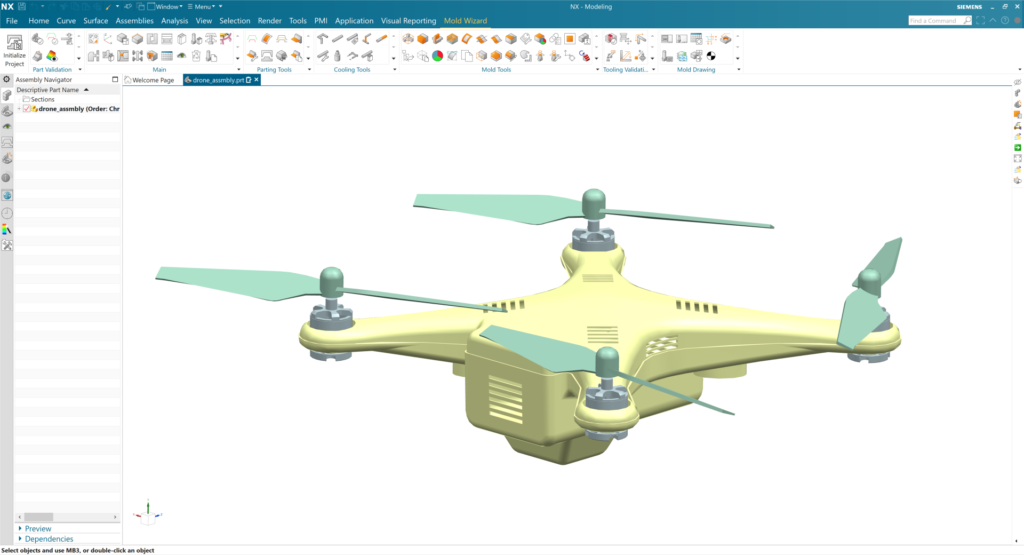
NX Mold Design is built on NX, so I had robust design tools for working with the CAD geometry. Less capable systems can handle basic parts and molds, but because NX Mold Design uses Synchronous Technology, it is well suited to more complex shapes such as this quadcopter top cover. In addition to the typical mold design tasks such as defining parting lines and sliders, patching surfaces and so on, I added ribs to the part to strengthen it and to improve plastic flow. Synchronous Technology made this work fast and intuitive.
To capture the designer intent in the CAD model, I included product and manufacturing information (PMI), such as tolerances and surface finish. This PMI data would be used later to automate CAM and CMM programming in NX, something that will be discussed in later posts. The PMI-driven process allowed us to capture and digitally transfer the design intent all the way to production, while automating the end-to-end process.
Beginning the mold design with CAD data established the foundation of the Digital Machine Shop – a digital representation of every aspect of the mold that flows through its entire development process, from design to machining (both subtractive and additive in this example) to the final inspection.
Disrupting the moldmaking industry
Watch this on-demand webinar about how one of our customers, iMFLUX, uses NX Mold Design to enhance productivity and innovate faster.
Design Automation
A key strength of NX Mold Design is how much of the mold design process it can automate through the use of its built-in Mold Wizard technology. For example, using the CAD geometry of the quadcopter, NX Mold Design automatically created the negative – the precise geometry of the casting mold. Also, NX Mold Design provides a structured workflow based on expert best practices. This advanced capability guided design engineers through a step-by-step, efficient process that also integrated some of the more complicated steps into automated sequences. But I’m getting ahead of myself . . .

Could this Part be Molded?
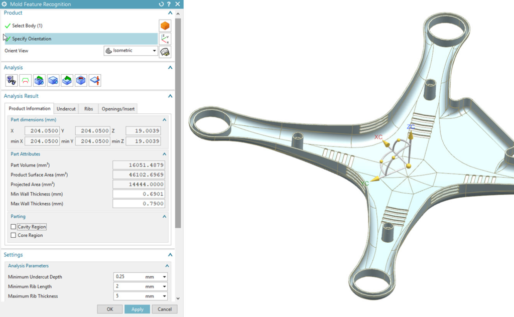
Before we went too far with this project, I wanted to check our part for moldability. I had a visual check of the core and cavity sides, but I also used NX Mold Design tools to automatically obtain information about draft angles, undercuts and sharp corners – elements that would make the part impossible or difficult to mold. The software made the results easy to interpret. For example, wall thicknesses were shown as color-coded areas on the part model.
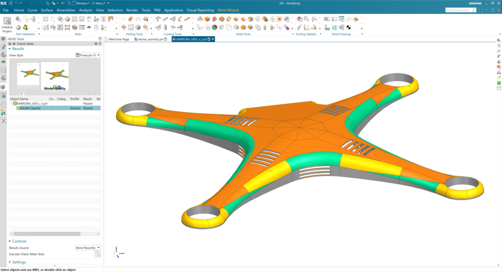
The draft analysis showed some areas with insufficient draft. Again, Synchronous Technology in NX came to the rescue here as it makes it easy and straightforward to work with imported geometry. I edited the geometry to increase the draft and re-ran the analysis to make sure I had it where I wanted it. By catching problems like this early, I was able to help avoid the wasted time and effort that could have occurred if we sent our supplier a part that couldn’t be molded as designed.
Mold Flow Simulation
Mold flow simulation was another step I took to ensure that we’d have no surprises when it came to actually molding this part. A mold flow simulation on part geometry can identify problems such as weld lines, short shots, air traps and warpage early in the design process when it’s not as costly to fix them as it would be later on.
I didn’t have to leave the NX environment to do this. Advanced mold flow analysis functionality – NX EasyFill powered by Moldex3D – is fully integrated within NX Mold Design.
Setting up the simulation was a straightforward and quick. First, I added components such as runners, gates and a cooling system to our part geometry. Gate and runner wizards gave me many possibilities to choose from. There is even a gate location wizard that helped in determining where to place the gates. After I established the conditions for the analysis, the report format and so on, I was good to go.
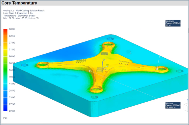
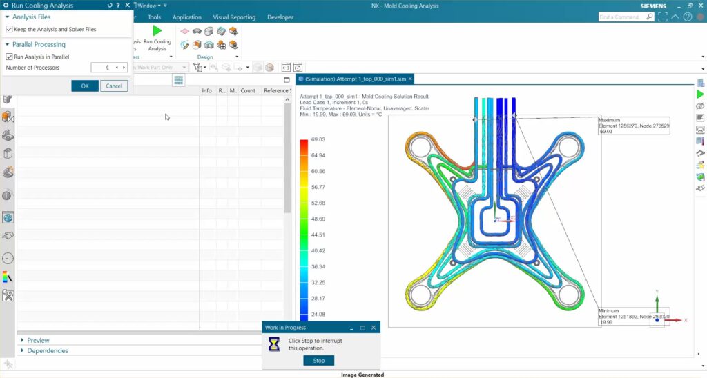
Another powerful NX Mold Design technology I used was Mold Cooling Analysis. I wanted to put some thought into cooling since it is the part of the injection molding process that takes the most time, and for that reason, mold cooling time ultimately plays a big role in the profitability of a plastic product. Previously, calculations of cooling took a long time, and users had to switch between CAD and CAE systems. Now it’s all in one system so the workflow is much faster. For this part, the simulation confirmed that the 3D conformal cooling channels I created would lead to the shortest cooling times (up to 10% lower than traditional cooling channels).
Estimating Tooling Costs
As it turned out, I didn’t find any problems with the mold flow that required me to change the part geometry. If that had been necessary, any of the changes I made would have been visible to all of the following steps in the mold design process, including machining, inspection and so on.
I did make another change to the part, however – not to improve mold flow but to save tooling costs. Moldmakers spend a great deal of time and money each month quoting mold costs, often for parts that will never become actual jobs. I was fortunate to have access to a quick way to calculate tooling costs, NX Feature2Cost, which recognizes cost-driving geometric parameters such as surface area, volume, wall thickness, feature ribs, openings and undercuts.
In this case, the initial design used cooling vents in the quadcopter cover that required a very small (2.5 mm) tool. I spread them out so that a standard 4mm tool could be used instead. I did this during the mold design process, knowing that the change would seamlessly flow to all subsequent operations.
Reuse Libraries
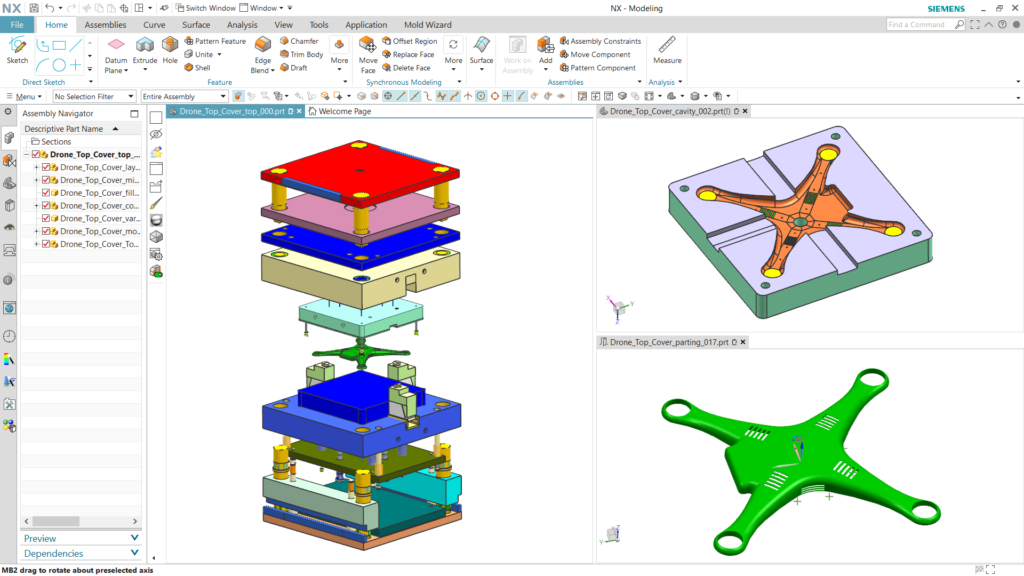
As I built the rest of the mold assembly, much of the work was already done for me. For example, the software automatically detected the correct size for the workpiece, although I could have changed that if I’d wanted to. Also, patching openings (in preparation for creating the mold’s cavity and core) was simplified by the use of advanced tools. These made patching the openings for the cooling vents much simpler than it would have been using standard CAD commands. The software guided me in creating the parting lines and once that was done, a single click performed the core-cavity extraction.
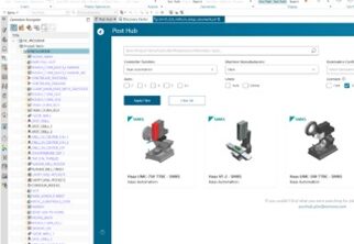
For the rest of the mold assembly I used standard mold components from the NX Standard Parts and Mold Base library. This database includes an extensive list of standard bushings, lifters, sliders and other components, as well as mold bases from a variety of vendors such as DME, Futaba, HASCO and LKM. After finding the mold base I wanted, for example, it was a simple matter of dragging and dropping it into the design. It’s also possible to create your own reusable components and save them in custom libraries.
Moving to Machining
At this point, my mold assembly was done. Creating 2D drawings of a mold assembly is an automated, one-click process so I went ahead and created drawings for my records. The 2D drawings are optional as I’ve added the PMI data earlier that can seamlessly drive the downstream processes such as CAM and CMM programming.
The next posts in this series will explain how the rest of the team leveraged the digital data I created using NX Mold Design – the Digital Twin of this mold – to streamline the NC programming of the mold faces and mold structure components. We’ll look at core and cavity programming, mold plate programming, process validation, postprocessing, and the creation of shop floor documentation.
Award-winning mold manufacturer relies on NX
Check out the customer success story on Cavalier Tool and Manufacturing and how leading-edge technology helps the mold manufacturer succeed in challenging mold projects.
Learn More
Check out all the blogs in our digital machine shop series featuring the creation of a quadcopter and published weekly.
In case you missed it, read last week’s blog here, and check out the next blog in the series on CNC programming!
![Digital innovation energizes small manufacturers’ business [CIMdata commentary]](https://blogs.sw.siemens.com/wp-content/uploads/sites/15/2023/02/Pfeiffer-use-395x222.jpg)