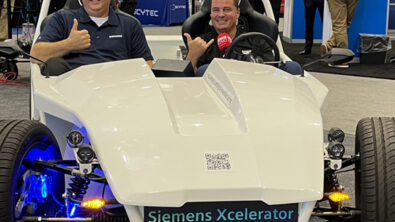
EV component manufacturing – Part 5
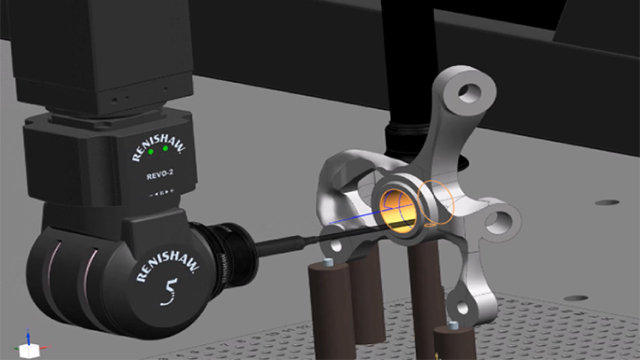
CMM quality control inspection
After designing our steering knuckle, optimizing it for weight, durability, and manufacturability, we needed to address quality control for our industrialized process. Joe, our part quality engineer located in Orlando, was responsible for programming our CNC machines and took on this critical quality control function.
Starting in the design phase, we took advantage of the PMI (Product and Manufacturing Information) capabilities in NX. The design team used PMI Advisor to validate that the tolerance and dimensional information that were applied to the model were syntactically and semantically correct. PMI Advisor helps the user with geometric and dimensional tolerancing (GD&T), a challenging topic, but a very important step in the part manufacturing process. Using this application, the team easily managed complexity, and had confidence that the information applied to the model adhered to the relevant industry standards.
Product and manufacturing information holds the non-geometric attributes that are required for the manufacturing of product components and assemblies. PMI can also include geometric dimensions and tolerances, 3D annotations (text) and dimensions, surface finishes and material specifications. PMI is embedded in the 3D model as part of the model-based definition approach. This information can then be used by several downstream processes eliminating the need for drawings and automating the process. For example, NX CAM and NX CMM can access PMI directly to automate programming.
Automating CMM inspection programming
The tolerance information used in manufacturing is traditionally captured in a drawing. However, in the digital machine shop environment, this information gets added to the digital twin of the 3D part model as PMI in the design phase (a model-based design and manufacturing approach). With that, all instances of the design and manufacturing process have the most current version on hand. Moreover, notes that are typically penciled on the paper drawing can be added to the model as a PMI. This means that you don’t have to send the final paper drawing back to the designer to have it updated and made into a final as-is drawing. All critical-to-quality tolerances are available to be consumed directly in the CMM environment without additional interpretation.
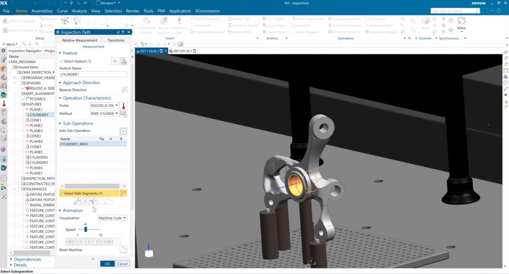
NX CMM automates the creation of inspection features, tolerances, and paths using the PMI that was added during the design process. This is literally a one-click operation. NX CMM offers a wide selection of inspection path types ranging from points, scan line, scan curve, scan arc and full 5-axis curve scanning, giving Joe all the tools that he will need to define the full inspection process that he will run on the CMM machine.
This ensures accelerated programming, as well as efficient and accurate part inspection on the machine, whether dealing with linear tolerances or feature control frames.
Importantly, NX CMM manages all this inspection-related data within a single file, which is consumable directly into the quality environment. This reduces mistakes that are made when the CMM programmer needs to interpret drawings and manually key in data.
To prevent any possible mishaps on the shop floor, Joe needed to ensure that the inspection path wouldn’t cause issues like collisions with obstacles on someone else’s machine. To achieve this, Joe validated everything with machine code simulation using a digital twin of the CMM.
Resolving out-of-tolerance situations with CMM inspection data analysis
With a fully validated CMM inspection program, Joe transferred the part inspection program to the machine, ran the inspection, and imported the results back into NX CAM to compare the actual results to the nominal part model. Utilizing NX CMM’s data analysis capabilities, Joe evaluated ‘as-built’ measurements alongside ‘as-designed’ models, facilitating effective quality improvements. CMM measurements are integrated into NX, enabling a detailed comparison to associated tolerances based on ANSI, ASME, or ISO standards.
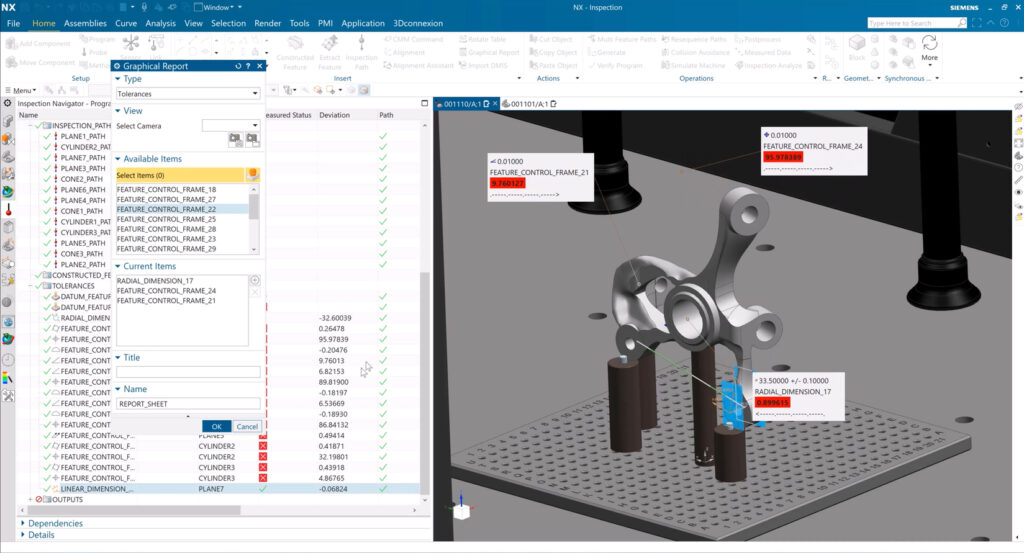
The nominal comparison provided a graphical visualization of which features passed, which ones failed, and what features might require rework. This came in very handy when we encountered an out-of-tolerance situation. The arm on the knuckle that connects to the outer tie rod with a ball joint had some residual stress and ran out of tolerance upon inspection.
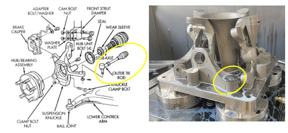
Because NX CMM is part of an integrated digital machine shop environment, Joe (CMM programmer) could collaborate with the all engineers on the team, including Adam (additive manufacturing), and Carson and Joe (CNC programmers) to determine how they needed to handle the out-of-tolerance situation.Since the arm was connected with a ball joint and would need to undergo alignment anyway, they were able to loosen the tolerance on this specific feature for now and work on the heat treatment process to resolve that problem in the future. Just as any other future design adjustment, this change would be available in all product and process data, maintaining associativity and traceability. The NX CMM data analysis confirmed that all other features were in tolerance. We could then approve the part for assembly on the eRod and perform final test procedures under real world conditions, which included alignment of the drive train and a test drive on a restricted track.
Integrated CMM inspection programming improves quality and productivity
NX CMM Inspection Programming reduces programming time, frees up expensive CMM machines, and ensures a fast response to design changes. In summary, quality control is transformed in the digital machine shop using the digital twin so we can:
- Program automatically, using PMI attached to solid models
- Validate programs using machine simulation
- Measure quickly, with high-speed inspection methods
- Analyze measured results, comparing as-measured to the as-designed master model
All part requirements are inspected in adherence to company standards, supported by swift and efficient design change propagation across the entire process. This is made possible through a unified CAD, CAM, and CMM system, ensuring seamless integration and real-time updates. This system streamlines workflows, fosters collaboration, and allows for quick and efficient comparisons between the “as-built” and “as-designed” states without the need for imports or exports – everything is readily available in one well-managed environment.
In our next blog, we move to the actual CNC machining process, talking to Chris Pollack to learn how he manufactured the spindle for the wheel knuckle on a lathe machine equipped with a Sinumerik controller.
Stay tuned to our next post to see how things turned out for our team!