EV component manufacturing – Part 4
CAM / CNC programming: Automatically generate high-performance toolpaths with NX CAM
At the end of our previous blog, we had completed the engineering phase of the new steering knuckle using the latest topology optimization technology in NX CAD and the advanced additive manufacturing capabilities in NX AM.
In this post, we move into the CNC programming phase, where we used NX CAM, a manufacturing component of the Siemens Xcelerator portfolio, which provides comprehensive programming capabilities in a single system.
We’ll show how utilizing digital twin technology helped us refine product design and manufacturing process before we ever utilized any physical resources. Our NC programmer’s expertise combined with advanced CAD/CAM capabilities in NX allowed us to simplify programming and reduce machining time.
Seamless collaboration across design, additive, and CAM engineers
As we begin our CNC programming phase, Carson took the lead on the project. He is a highly experienced NC programmer, specializing in 2.5-axis, 3-axis, and 5-axis milling. Having worked with several machine tool OEMs, he also brings a lot of hands-on machining experience to the table. Working out of Charlotte, NC. Carson accessed the latest part design from Teamcenter, our digital backbone, ensuring that he is working with the most up-to-date version.
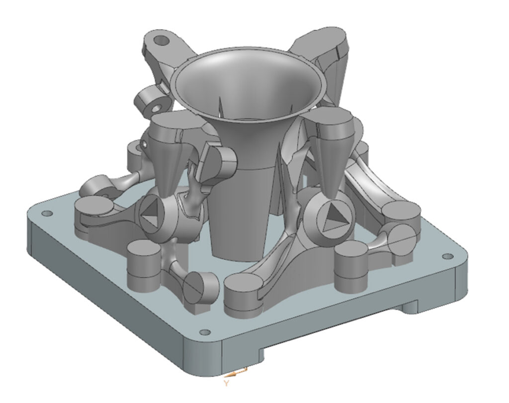
Carson was involved in the design phase early on to make sure that the printed part would be manufacturable downstream. For instance, he suggested changes to the design of the arms of the knuckle and the center bore. The updated design can easily accommodate different support structures that made the manufacturing process more efficient. He also recommended the creation of a triangle feature in the center bore in order to clock the part and know its exact location on the machine. This is one of the important benefits of the entire team (CAM programmers, CAD designers and additive engineers) working concurrently using the same data set.
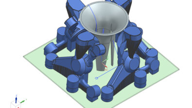
We arranged the parts and supports on the build plate so it could be manufactured at scale, with 4 parts to be printed on a single 300mm x 300mm tray. This was important because it increased the part density on the machine, which gave us 4x the output in manufacturing.
The build tray itself was outfitted with holes for pull studs to connect to a powerful and quick changeover system. The cylindrical features allow the tray to be popped in and out, reducing set up time and increasing the repeatability of the process.
To ensure the parts were stable during cutting, a sacrificial structure in the center was designed to use little material, but be strong enough to hold it all together and eliminate the risk of vibration. This “trombone” structure connects to all 4 parts, which allowed us to machine most of the features in OP10 (the first setup and clamping of the part machining process) and remove most of the support structures, plus the bit of material from the top edge of the part that connected it to the trombone.
Accelerating manufacturing using advanced CAM software
To program and machine the printed part, we used the comprehensive capabilities of NX CAM. CNC machining was needed to meet the dimensional accuracy and surface finish requirements. In this section, we will highlight only a couple of these capabilities. To learn more, you can check out the knowledge articles on the NX Manufacturing community.
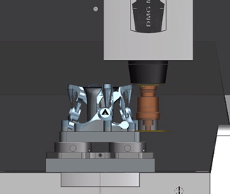
Starting the process with the newly developed 3D Adaptive Roughing operation that enables high material removal rates. Carson used this advanced roughing technique for the center bore. In addition to the efficient toolpath, this advanced operation features accurate tool holder collision check, eliminating any questionable situations well in advance of turning on the machine.
In the process, Carson used the multi-axis deburring function to make sure the part would be free of sharp edges after being removed from the printing structures. This is required from a safety and quality perspective.
With NX, you can automatically program all the edges for deburring. While that traditionally had been a complex or even manual programming process, Carson was able to do it with just a few clicks.
The final operation in process step OP10 was to cut our part off the tray using a disk cutter.
This is when a function like Distance Measure with Pick on Path comes in handy. It provides a quick way to verify toolpath related measurements. In this case, it helped us quickly decide how deep to run the disk cutter, ensuring that the desired break-off ledge will be left on the part.
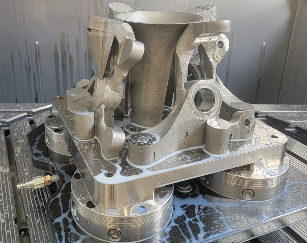
After the cut off operation, the part is only connected to the trombone with a tiny bit of material at the top edge of the part and a break-off ledge at the bottom that can be easily separated by hand.
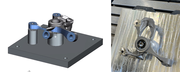
With the parts removed from the build tray, we can now flip the part and machine the “backside” features.
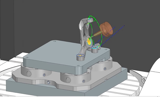
For the OP20 manufacturing step, Carson designed a fixture using a library of 3D parts, such as clamps. That was easy since NX is not only a CAM software, but also includes industry-leading CAD design functionality. An additional stud was added at the brake caliper arm – just for peace of mind. These fixtures were very low cost, and we could easily make them in our own shop.
Ensuring safe machining with accurate and integrated simulation
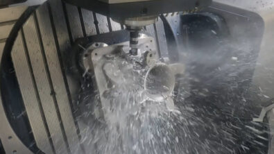
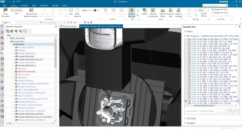
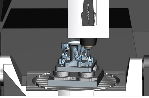
For the machining simulation of the part in NX CAM we utilized a digital twin of the DMG MORI DMU 85 monoBLOCK machine tool. This enabled us to validate ahead of time whether there would be any collisions between the machine and the part, or between the machine and itself, such as the spindle hitting the table.
Clearance was tight in some of the operations due to complexity of the 3D printed part. Using the NX simulation, we could visualize the built plate, fixtures, tools, holders and the entire CNC machine working envelope to see exactly how our machine was going to cut the part, including material removal.
The G-code-driven simulation allowed Carson to verify that the tool paths were collision-free and all features could be accessed safely. For the simulation, he used the same NC-code that would control the machine tool.
Using the accurate simulation in NX CAM, Carson was confident about the entire machining process, including one of the drilling toolpaths. Its moves were very tight, but he validated the operation and confirmed that it was collision-free.
It is important to mention that by collaborating with the design, additive, and manufacturing engineers from day one, Carson made sure the parts are positioned and angled on the build tray in a way that all the features can be machined safely.
The CNC programming phase of our steering knuckle manufacturing project showcased the power of using advanced CAM software that provides some important advantages, including:
- Automated programming
- Integrated simulation
- High performance machining
Additionally, using NX software enabled our team of CAD designers, CAM programmers, and additive manufacturing engineers to easily collaborate, which is critical for any manufacturing process.
In our next blog, we will look at how we tackled our CMM quality control and inspection process.