NX | How to series | Modeling a part for the first time
We’re incredibly excited to be bringing you the first video of a brand new series for NX™ software. Throughout the course of 2025, we will be bringing you a range of videos focusing on a complete end-to-end workflow. The video will include typical steps you’ll need to take, and best practices we’d recommend you implement into your workflow.
The first video entry into the new series will explore the steps that go into modeling a part for the first time. We’ll show you everything from opening a part file, understanding the layout of NX right the way through to creating your design, and finally polishing your design for added quality.
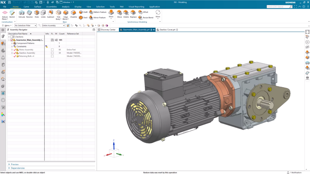
Throughout the course of this how to blog, we’ll be focusing on this gear motor assembly. We’ll show best practices to create a gearbox cover using a range of tools within NX.
Creating a new file
It goes without saying, the creation and modeling of any new part is to open a new file. This will give you the blank canvas you need in NX to start working up your project. Similar to a new Word document, simply select the File option and then select New. What you will see is the ability to choose from a variety of template parts that are prepared with system settings optimized for each specific workflow described by the naming of the template.
You’ll notice several category options at the top of the page, each representing a discipline that you could work in. These different disciplines will have multiple template parts to choose from, giving you a head-start for your creation. For the sake of today’s’ demonstration, we’ll be focusing on the modeling discipline and application. Even in here, you have a range of options to choose from, each one providing different design capabilities and interfaces that are optimized for your workflows.
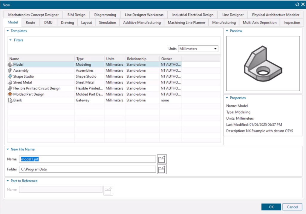
There’s a couple of key pointers to consider when you’re setting up your part:
- When you create a new part, you’ll have units drop down box. This is where you’ll be able to select and define the measurement system for your design.
- Staying organized is crucial to stay efficient with your design, so use an organized system that makes sense for you and your workflow. It’s important to save early and often, ensuring your design work is protected and revisions are available downstream.
Investigating the basic layout of NX
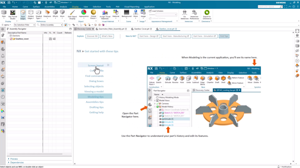
Once you’ve configured the previous settings and created your first empty part, you’re ready to familiarize yourself with the screen layout in NX. At the top of the screen is the title bar, which shows you the application you are working on.
Underneath this, there are a number of tabs to assist with the design process. We’ve identified the most commonly used commands and made them easily accessible within the Home tab. Many of the more complex design actions will require the use of other tabs.
To change the application you are working in, select the Application tab and the new application you need. Another important feature to point out is the resource bar, which is always pinned to the left hand side of your screen. Once again, there are a range of tools to assist with your design process.
A key tab we want to draw attention to is the Part Navigator. This will organize all of the features that you’ll create throughout your whole design process. If at any point within your workflow you want to go back and make a change to a previous feature, this is the place to look.
You’re now ready to start creating your part. Let’s dive in!
Sketching the shape for a new part
Any new creation generally starts with a sketch. A sketch will lay the groundwork for more complex processes later on. The sketch command can be found under the Construction group within the Home tab. When the command is selected, you’ll see a prompt to select the plane the sketch will be created on. At this stage, it’s not important, but once you’ve started to build the sketch using other features, it’s significance will be more noticeable.
IMPORTANT TO REMEMBER:
To make life easier for you as your designs progress, make sure you create sketches that are simple, and are also fully defined.
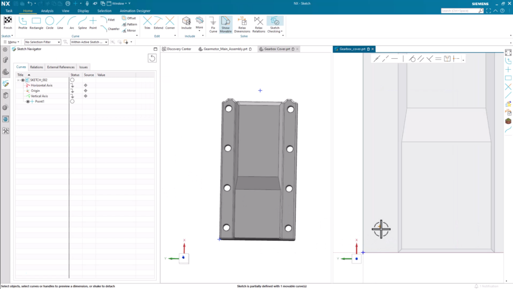
The Sketch Navigator
The Sketch Navigator in NX is your best friend; it’s a centralized and intuitive interface for managing your sketches. Each line and curve that is produced will be stored and organized here, so you’ll be able to track new changes in real-time. It doesn’t matter the industry you work in; fully defining each curve and line is always a crucial aspect to consider.
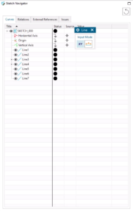
Within the Curves tab, the status column shows if a curve is fully defined or not, providing a good indicator to allow for your sketch to behave predictably, especially during modifications to the model. A black circle indicates a sketch is fully defined, and a white open circle shows there are still dimensions that you need to address. The goal here is to ensure that your sketch is fully dimensioned, with each line and curve having an attributed black circle.
Trim Command
Make sure to take advantage of the Trim Command; a tool that will remove sections that obstruct the connection to the newest lines for the body of your sketch. NX will automatically update the shape of a sketch when clicking and dragging an existing line.
Using the Extrude tool
At this stage, you’re now ready to turn your 2D sketch into a 3D product. The most common way to do that is through the Extrude command within NX. The command is used to create a 3D shape by extending a 2D sketch along a straight path to form a prism. This will usually be perpendicular to the sketch.
It’s important to note that whenever you are extruding a sketch, you’ll have to select a distance for the sketch to extend to.
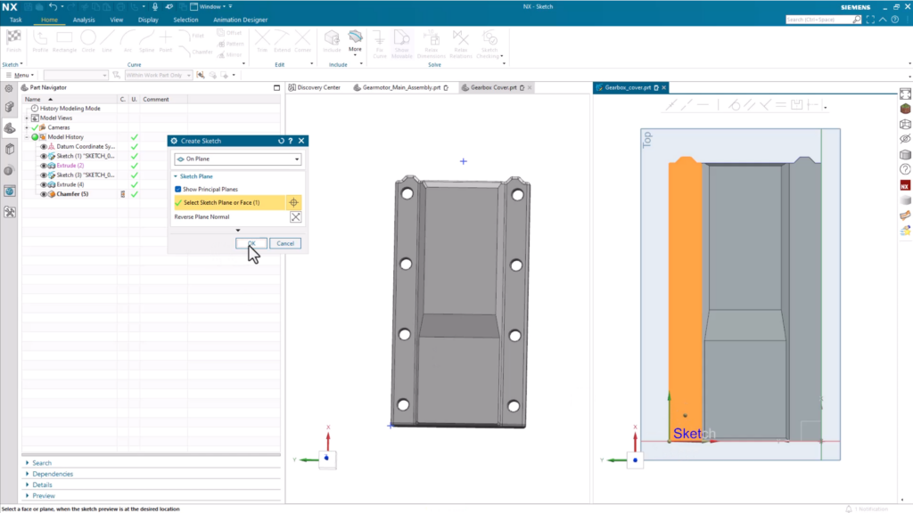
For this particular use case, we’re going to create the second part of the gearbox. This time, when we create a new sketch, we’ll place it on an existing face for the body we created earlier. This time, we’ll leverage the Profile command tool.
Profile command
With the Profile tool, you’ll be able to quickly define the outline of your part with a series of connected lines in a string. The end of the last curve becomes the beginning of the next curve The value of the Profile command lies in its flexibility and efficiency. It lays the foundation to be able to experiment with different ideas, giving you the tools to refine and innovate on your designs.
Chamfer command
Another feature which you can implement when creating a model is the Chamfer command. It’s a handy tool when you are looking at optimizing your part’s ergonomics and manufacturability. In this use case for the gear box, we used the tool to mimic the draft along the cover currently used on the gearbox.
Adding Holes
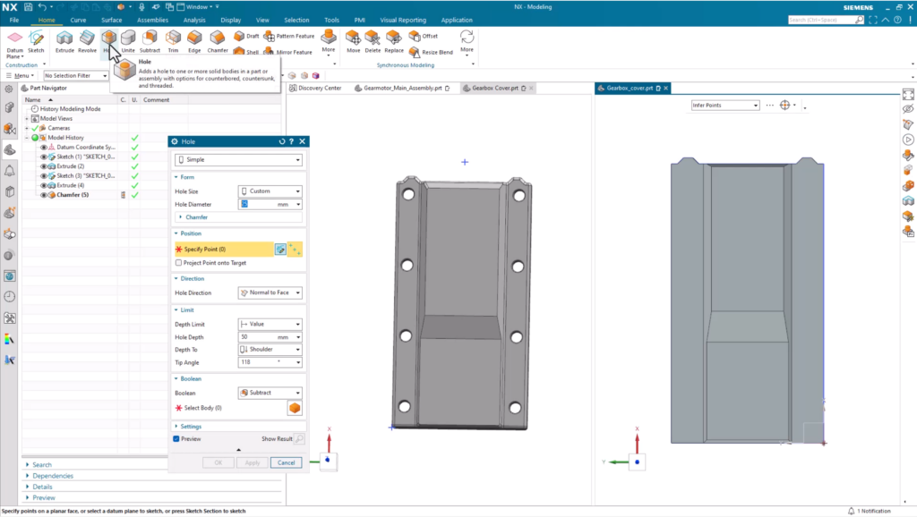
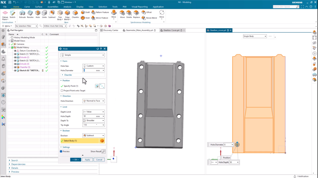
Placing the Holes
There may well be a time where you need to create a set of holes for your part. We’re going to show you an easy way to create these holes using the Pattern and Mirror commands. But first, place the master hole to be patterned and mirrored. This command can be found in the Home tab within the base group.
When you place the hole, you’ll need to use the Sketch Point tool that is built into the Hole command. This will allow you to properly place the hole at an appropriate distance from the sides of your part. With that step completed, the next and final step is to set the hole diameter.
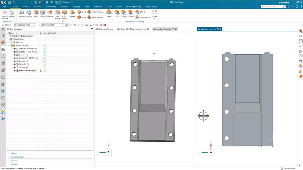
Pattern Feature tool
You could go ahead and manually repeat this step to create all the holes you need. What you’ll find is that this approach can waste important time. With that in mind, we’ll show you how you can use the Pattern Feature tool to make this step quick and easy. It’s a powerful tool that enables you to create multiple copies of a selected set of features or geometry in a fraction of the time.
The Pattern Feature command enables you to create linear, circular, or rectangular patterns. For this demonstration, we’ll be using the linear pattern to re-create the holes along the vertical axis of the 3D body. You’ll have complete control over the spacing to apply between your replicated holes. In this instance, we’ll use count span, which allows us to specify how many times the feature will appear and the distance it will span.
Mirror Feature tool
There may be a time where you need to copy the holes that you have placed on the opposite side of your part, similar to our gearbox cover. You can achieve this in NX using the Mirror Feature tool a handy option to reflect copies of your originally selected features. It works by defining an existing plane, a planar face, or a user-defined plane. For the gearbox cover, it’s a case of creating a new plane that is offset so that the part can be split in half. This will mean that our existing hole features are identically spaced along the opposite side of our gear cover.
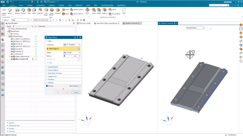
Edge Blend
We’ve almost re-created the gearbox cover using a range of tools within NX, but there’s one more step to take. You’ll notice that the corners for the cover are still pretty sharp. So, let’s take a look at a tool to round them off; the Edge Blend command. It’s a tool you can use to create smooth, rounded transitions between intersecting surfaces or edges. Not only will it make corners smoother, but it can also help the aesthetics of the part, as well as its structural integrity.
Refining the final product
At this point, you’ve created the basic shape for your part and optimized it using a range of tools in NX. The modeling isn’t quite done. There are tools available to you to make your creation a more presentable end product. There’s a couple of options available, both of which can be found within the Display tab at the top of the page. Let’s take a look.
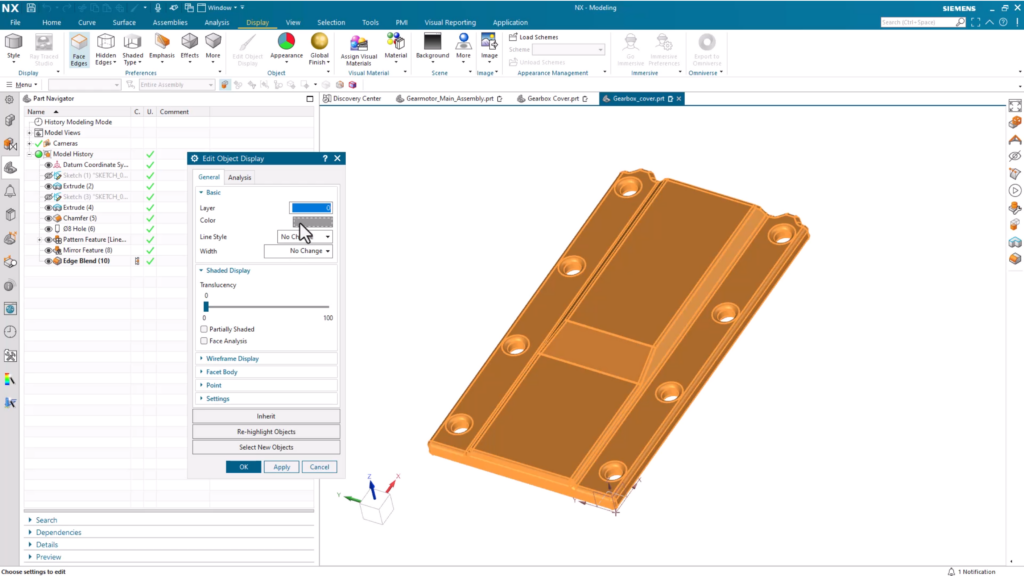
Edit object display
Edit object display is a tool to modify the visual representation and display properties of a part within the modeling environment. Object visibility, color and transparency can be tweaked, which enhances visualization of a part without ever changing the actual geometry. It’s typically used to highlight specific parts and assemblies, distinguish between different components and improve visual clarity between design iterations.
Assigning visual materials
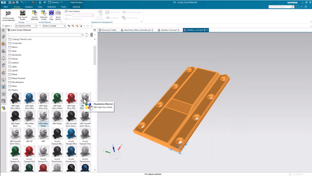
Assigning visual materials take it one step further. NX comes with a range of out-of-the-box materials that you can assign to your part for a more accurate material representation. You can also create your own materials from scratch if you can’t find the material that you are looking for.
On top of this, assigning materials lays the foundation for further simulation and analysis to help with downstream processes. When applying new materials, key qualities such as density, elastic properties and thermal properties are included. The result? More accurate and precise testing when using analysis tools like Performance Predictor and Sustainability Impact Analysis.
Continue your journey with NX
How to use Discovery Center
A great place to continue learning about the key capabilities with in NX is the Discovery Center. You’ll find everything you need to enhance your skills and learn about the game changing capabilities. There’s a dedicated spot for getting started content, as well as other links for additional tutorials and resources to continue your development further.
Other useful links
Visit our Tips and Tricks YouTube channel

Take a look at the NX design blog