Getting started with Mold Wizard | NX Tips and Tricks
We’re continuing our Tips and Tricks series for the June 2023 release of NX™ software. New capabilities added to this release are based on your feedback, with the goal of enabling you to achieve your workflow goals.
In this episode, we’re continuing to focus on new tooling capabilities, with a focus on NX Mold Wizard. Let’s take a look!
What is NX Mold Wizard?
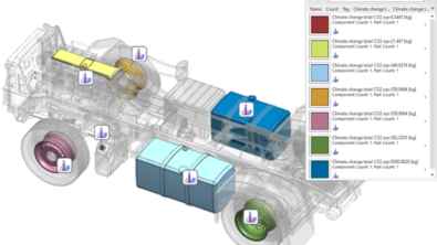
NX Mold Wizard gives you a complete working environment in which to design molds for injection-molded plastic parts. You can produce a fully customizable mold cost report, and rapidly generate a fully-featured mold design.
Use Initialize Project command to begin mold design
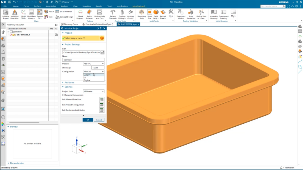
The first step in the workflow enables us to start the mold design process, and can be done by using the Initialize Project command. The command can used to specifically create new mold design projects from bodies and curves. Furthermore, you can add additional products to existing projects to create a family mold.
When the command is selected, you will be prompted to select the regions to be included. You can select the file, path and name, and the material that is used. With the material selected, shrinkage values are automatically determined. It is important to remember that these values can be manually set too.
Can your parts be manufactured by traditional mold processes?
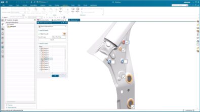
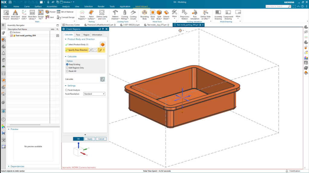
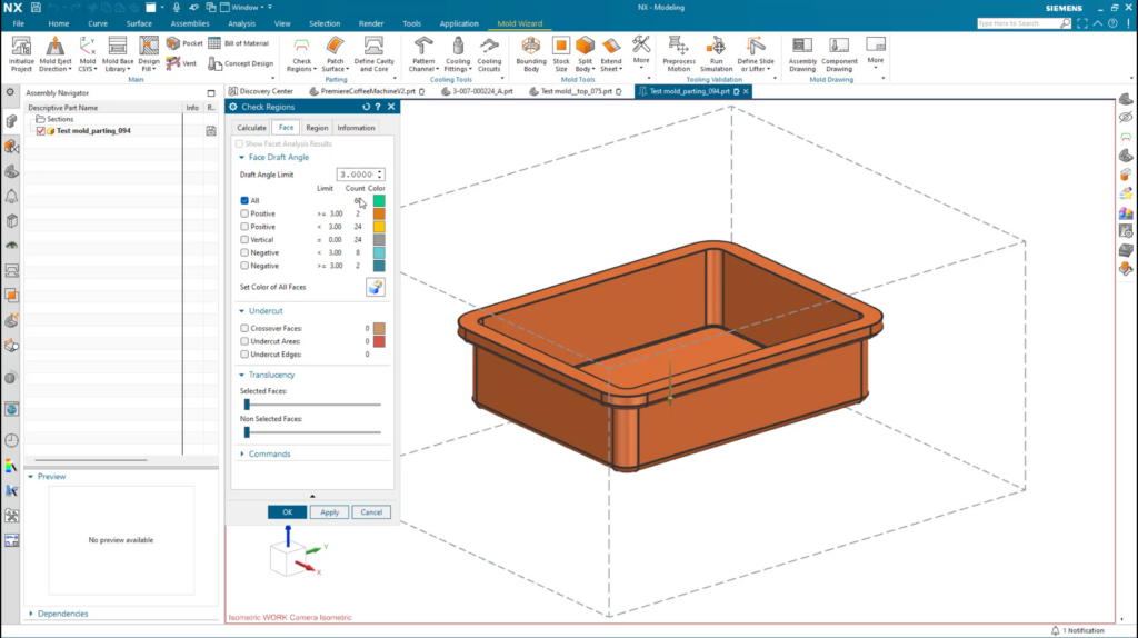
Next, it’s important to determine whether your mold can be manufactured through traditional mold processes. Traditional processes can include injection molding, die casting, and sand casting. To start the process when using the Check Regions function, you will be prompted to select the body of the part, the draw direction, and the calculation settings. Once finished, it is important to use the Face tab to
- Analyze the model faces for draft angles
- Color code the model according to draft conditions
- Locate undercut faces and edges
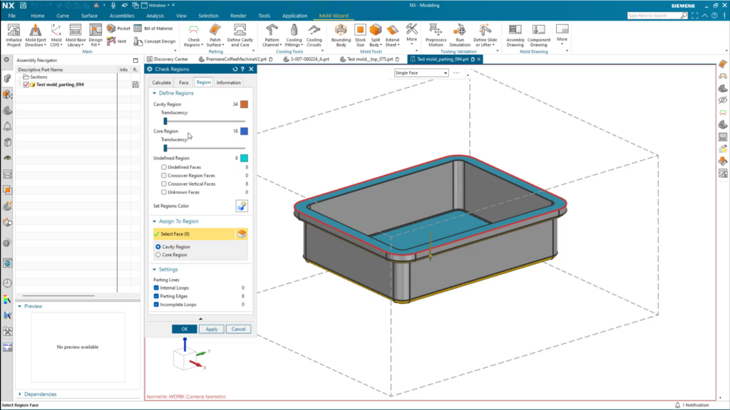
Additionally, the region tab can help identify any parting loops, internal loops, parting edges, and incomplete loops within your mold.
To round off the Check Regions command, you can also define information for your mold. In here, you can check and edit face properties, model properties and sharp corners
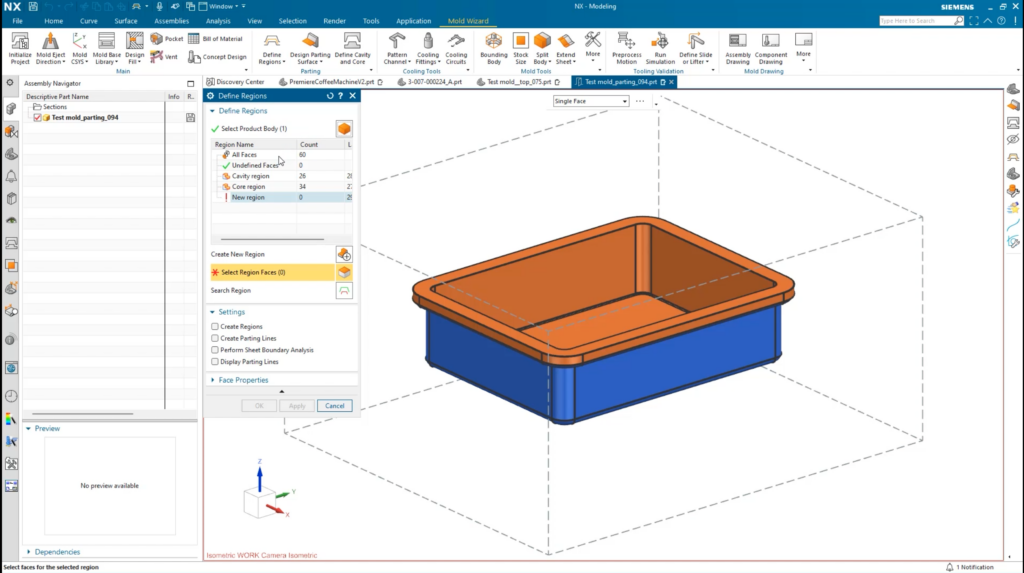
Create cavity and core region sheets with the Define Regions command
We’re now in a position to create the region sheets and parting lines for our design. And this can be achieved by utilizing the Define Regions command. When the command is selected, you’ll see a table which organizes the number of faces, cavity regions, core regions, and new regions. You’ll be prompted to select a product body and regions faces from their part.
Important step:
The parting lines have been created, so we can click Design Parting Surface, where the parting lines have been created, and click OK.
We’re almost complete, but there’s one final thing we need to do. Select the Define Cavity and Core option, and click OK. With that, the mold is now prepped to add cooling channels and features.
Continue your journey with NX
Take me to the NX design blog 📚


Contact the NX team today 📲