Improving functional safety analysis

Functional safety analysis can be notoriously time-consuming and inconsistent. How can we improve it in modern design flows?
What Is functional safety analysis?
The ever-increasing complexity of modern-day electronic systems introduces many potential points of failure. In safety-critical applications, engineers must perform functional safety analysis to ensure that their designs meet or exceed safety standards and respond appropriately to failure events that could endanger human life, health, property, or the environment.
Failure Modes, Effects, and Diagnostics Analysis (FMEDA), pioneered by the U.S. military in the 1940s, is a widely used method for performing functional safety analysis across industries. However, FMEDA can be a tedious and time-consuming process. Subjective and varying interpretations by safety engineers increase the risk of imprecision and human error. In addition, FMEDA is typically performed late in the design cycle, so addressing identified issues often leads to costly delays and increased expenses.
Can FMEDA be modernized?
Siemens EDA and Modelwise GmbH are modernizing the functional safety workflow by introducing formalization and automation. Modelwise’s solution, Paitron, addresses many of the challenges associated with traditional FMEDA. Manual methods are replaced with an automated approach that enables accurate and efficient computation of FMEDA results. In Paitron, failure evaluation is performed using circuit simulation and automated reasoning, significantly reducing the time and effort required for comprehensive safety analysis. As a result, safety analysis can be performed early in the design process and repeated as needed throughout each design iteration.
An integrated FMEDA flow using Siemens HyperLynx AMS together with Paitron delivers even greater benefits and efficiencies. HyperLynx AMS is a powerful system simulator with versatile modeling, simulation, and analysis capabilities. It is directly integrated with Siemens Xpedition Designer, a schematic capture tool, allowing simulation models to be assigned directly to symbols in the PCB schematic. This enables a single design to be used for schematic capture, PCB layout, and modeling and simulation. Eliminating duplicate schematics reduces engineering cycle time and minimizes opportunities for errors.
A key benefit of interfacing schematic capture with functional safety analysis is the ability to generate bills of materials (BOMs) by extracting component property information directly from the schematic database. This enables the functional safety tool to automatically map components to failure-rate and failure-mode database categories—an otherwise tedious and time-consuming task. A unified schematic-based workflow also simplifies component database maintenance and ensures consistency across downstream tasks. For example, voltage and current ratings can be directly incorporated into functional safety analysis. This added accuracy and efficiency are unique advantages of this integrated workflow.
The integrated workflow in action
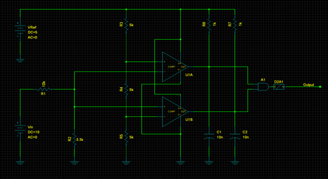
In a recently published white paper, we demonstrated the integrated HyperLynx AMS/Paitron workflow using two electronic designs. First, we analyzed a simple voltage monitor circuit by formalizing system inputs, outputs, and potential failure modes. This ensured an objective and traceable formulation that minimizes ambiguity. Component failure modes and rates were derived from industry standards SN 29500 and IEC 61709. These failure modes were injected into the simulation netlist and evaluated using HyperLynx AMS.

Once the analysis is complete, a detailed safety report is automatically generated, containing safety metrics aligned with the selected standard. Figure 2 shows an analysis summary highlighting key safety performance indicators (KPIs) defined by IEC 61508, including safe failure fraction, safety function failure rate, mean time between failures, and probability of failure per hour.
In most real-world design projects, PCB layouts involve far more than a simple voltage monitor. Typically, a PCB comprises multiple pages of schematics organized into functional blocks. In the full white paper, we present and analyze a PCB power converter system composed of five blocks—rectifier, controller, two DC-DC converters, and a voltage monitor—each exhibiting a level of complexity comparable to or greater than that of the voltage monitor example.
Download the white paper, Integration of Xpedition, HyperLynx AMS, and Modelwise Paitron for Automated Functional Safety Analysis, to learn more about this workflow.