MCAD Collaboration with PADS Professional Premium
One of the trends emerging over the past several years is packing more and more functionality onto ever decreasing substrates. The packaging – the enclosure of your product – is also getting smaller. To ensure your design fits into this enclosure, earlier communication with the mechanical engineering team is now a must.
How do you collaborate with the MCAD team?
Historically, communication is not done until the end of the design process, when the electronic designer sends a static file to the MCAD team to import into their tool. Over the years, many different file formats have been used to varying degrees of success, such as IGES, DXF, IDF, and most recently STEP. The two biggest issues with this legacy process are that it’s done too late in the design process, and secondly, that it’s a one-way flow of data. Any feedback provided from one domain to another would be given through some manual means – email, Word document, or a conversation, all of which are not optimal and can be error prone.
A better process exists
A new process has been gaining acceptance in the design community. Today’s MCAD collaboration enables true virtual collaboration between the electronic and mechanical design teams and tools. It leverages a best-in-class data exchange standard, the ProSTEP file exchange format (IDX) which allows data between these two differing design environments to be shared in a more fluid and dynamic way.
The new approach
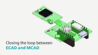
With PADS Professional Premium, the PCB design can be shared with the MCAD tool at any time. The process would start first by importing the mechanical information from the MCAD tool – card outline, tooling and mounting holes, keepout areas, and etc. Then, right after placement, true collaboration can begin. Via ProSTEP file exchange (IDX), the PCB design can be sent to the MCAD team. They can open the design in their MCAD tool – the same environment that they work in every day. The mechanical engineer can review initial placement, and in real-time, either approve this placement, or reject all or partial placement. If one component happens to be too tall for a specific spot on the board, causing a mechanical conflict, the placement can be rejected. The engineer can also move the component to a new location where no conflict exists. The electrical design team is then notified, opens the PCB design in PADS Professional Premium, where they can see the new proposal for placement. They then could also approve or reject this placement. This iterative collaboration will prevent late design engineering changes from occurring, which normally add significant delays to the completion of the design.
Native integration with Siemens
If you are using one of Siemens MCAD tools, SolidEdge or NX, with PADS Professional Premium or Xpedition, there are added benefits. Additional data objects are shared between both tools. More significantly, 3D models are exchanged between the tools, making 3D model creation and management much easier.
To learn more about MCAD collaboration using PADS Professional Premium, read our eBook.