E/E architecture diagrams demystified
Over a short series of blogs I’m going to attempt to answer some questions I get asked at conferences and events about E/E architecture diagrams, what they mean, how to read them etc… this will lead onto some discussion of the history, trends, and enabling technologies, I will link out to further reading, watching and other resources for those who want to dig deeper into specific topics.
Why do we need E/E architecture diagrams
Modern vehicles are complex systems, this applies to many domains, but especially the electrical, electronic and software systems which are made up of many kilometers of wiring, often well over 100 ECU’s (Electronic Control Units, small computers running embedded software), millions of lines of code, all of which interoperate, and are powered by, usually, several power networks. It’s therefor useful to be able to represent aspects of these systems in a simplified form, to describe the interconnections, functions abstracted from a fully detailed 3D view of where each of these many boxes are located and cable harnesses routed. Note, a digital connection to this data can help ensure accuracy and consistency, but we’ll come back to that.
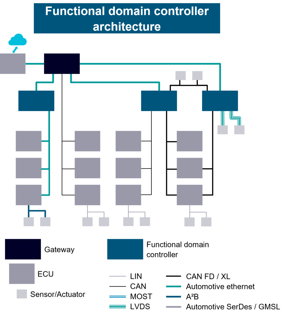
E/E architects use these diagrams to describe the E/E architecture of the vehicle, representing how the ECU’s are connected, and also in detail, as notes, or increasingly in the data model of the design, the functional allocations to each ECU, the signal routings, especially where multiple paths are possible. The E/E architecture is then consumed by a wide variety of consumers in the OEM, and some suppliers to ensuring ECU hardware, software, networks, and vehicle harnesses are all designed correctly.
An example might be Vehicle Speed, commonly the main source for this data comes from the ABS or Braking ECU, which usually has wheel speed sensors on each wheel, and some algorithms to account for wheel slip etc. This resolved Vehicle Speed can be shared with some obvious consumers such as the Instrument Cluster to display, and the Powertrain ECU’s, through to maybe less obvious ECU’s such as the Infotainment to adjust the volume to account for road noise, and Body ECU’s which might lock doors and/or close windows at high speeds etc. Usually the Powertrain ECU’s will also have an estimated speed based on Engine or Motor speed(s) and gearing, which can be used as a backup in the event of system faults to enable backup functionality, or as a cross check.
What else can be decoded from E/E architecture diagrams
Networks is where I began, as its the use-case I have returned to over my career most often, however, along with styling variations, orientation differences, many OEM’s use multiple diagrams for power networks, and other connections, and/or embellish these diagrams with much more information useful for the architects, and for the consumers within the OEM, from the EDS (Electrical Distribution System) teams designing the wiring through to those responsible for networks, ECU/module hardware and software, integration engineers and many more.
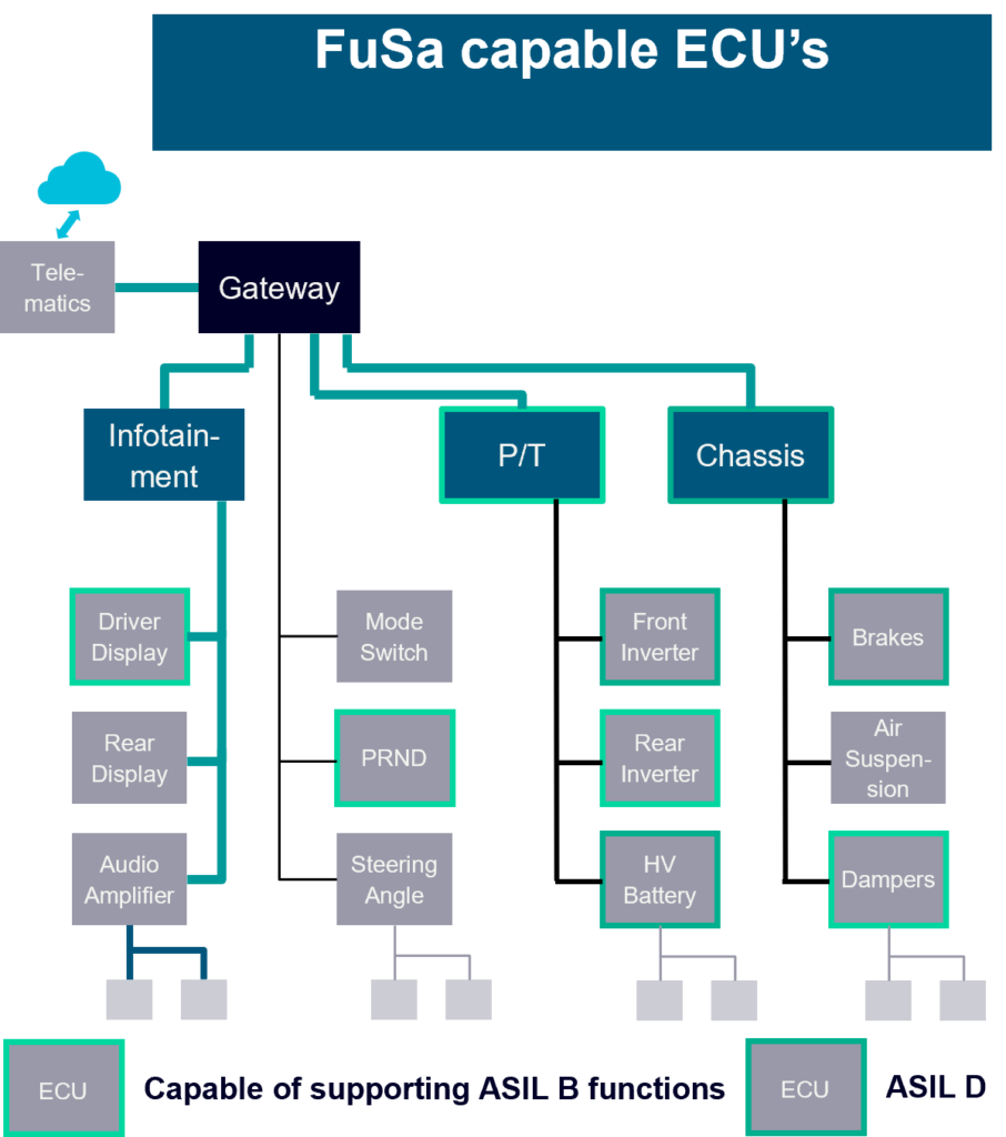
The properties described in the E/E architecture diagrams often define technical aspects of the hardware, software, connections etc., as the number of ECU’s and connections has increased understanding the different capabilities of the ECU’s to appropriate allocation of functions to ECU’s that can support the requirements becomes more important. This might be in some technical detail, for example, processor family, redundant processing, redundant power, memory types and many many more, or can be abstracted into what these specifications allow, in this case the ISO 26262 Functional Safety (FuSa) ASIL level that has been decided can be supported by an ECU.
Power networks
If we consider E/E architectures more broadly, then its not just networks that can be described visually, there are often hardwired connections, which maybe analogue or digital, communicating simple sensor values, through to redundant switch states to cross check with a network signal. There are many other properties and attributes as well, from the location of hardware cyber security elements, software stacks, processor and memory locations, and the power network, which maybe historically could have been a relatively simple 12v supply network with main and more local fusing, but which can easily now have multiple voltages, supplies, redundant grids/components, voltage converters and much more. A vehicle today commonly still has 12v supply, 48v is increasingly common for suspension, hybrid elements on ICE based hybrid vehicles, and a high voltage system is present on some hybrids and most BEVs (Battery Electric Vehicles), over 900v on some BEV’s.
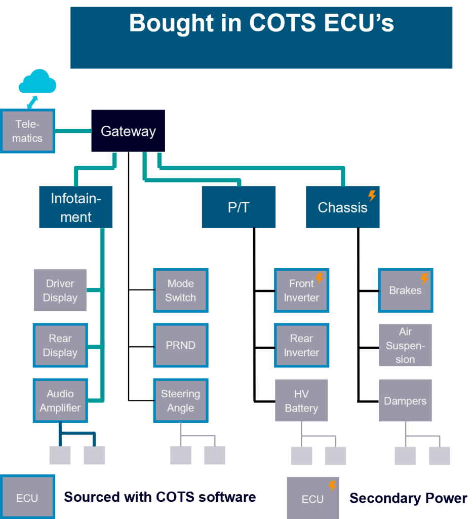
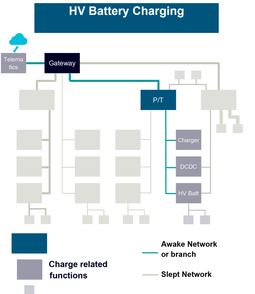
It’s worth noting that not all properties captured have to be technical aspects, some could relate to suppliers, or types of supplier, helping the architect consider the commercial and project timing aspects of allocating functions to different ECU’s in the architecture. A further consideration is to capture and consider operating modes of the vehicle, in the example below we have a low energy consumption mode, high voltage battery charging, but similar might exist for security systems, cabin pre-conditioning using climate control and many others. These modes are important to consider when allocating functions, and planning network connections to reduce the number of modules awake that aren’t needed, as well as the energy consumption, modes like charging can add significantly to the number of hours an ECU will be awake over the vehicle life, adding to the required durable life of the components within.
Tools
I’ve used simple hand drawn diagrams thus far to explain, and for many years, Visio or similar drawing tools have been a mainstay of these diagrams, which makes changes time consuming and with no underlying model there’s no automation to help the E/E architect check the model, and worse the consumers need to copy the architecture into other tools. Of course, there is a better way, and using modern design tools as part of an MBSE (Model Based Systems Engineering) flow, Siemens CapitalTM Systems Architect software being a great example, enables the import of SysML using Capital Software Designer with IBM Rhapsody or similar models, which can be allocated into the architecture on the upstream side, and export of the network architecture to Capital Network Designer, and ARXML data to Capital Embedded Integrator and Capital Embedded Virtualizer for integration, virtual validation and deployment.
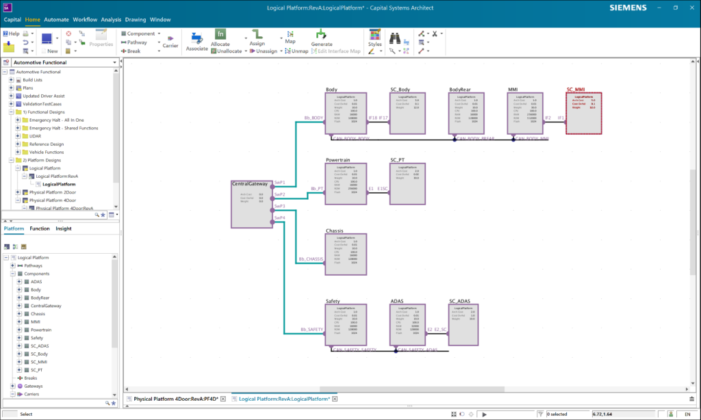
Also with a digital design of E/E architectures, we can define these attributes and properties, such as processor type, OS, and extend this set of properties, allowing the tool to validate architectural decisions, indeed some can be automated. We can further choose which of these properties are to be represented visually, and how. When considering power networks this might extend to ensuring the redundant supplies are correctly allocated, power or ignition modes governing when different ECU’s are powered/active are considered as discussed earlier and much more.
Summary
So in the first of this short series I’ve explained a bit about the origins of what we now describe as E/E architectures, Network architectures, represented in these architecture diagrams, how the complexity has increased, and the need to more formally design this aspect of the electrical system in vehicles has increased over time. To understand the basics of what is represented in these diagrams is fairly simple, ECU’s connected by networks and other links, powered by various supply networks, however they represent, and should ease understanding of what is now a very complex interoperating set of systems and subsystems, so attention to detail is important.
More on this topic to come soon, next I’ll cover some history… but if you want to learn more about E/E architecture now, the following reading links are a good place to start.
- White paper: Architecture-driven E/E systems development flow
- White paper: A closer look: Next generation electrical system platform development
- Fact Sheet: Virtual ECU software development

