How Close Can We Put Different Voltage Regions Together?
By Joe Davis, Mentor Graphics
Calibre tools provide a complete flow for implementing, optimizing, and verifying voltage-dependent layouts against the foundry’s signoff DRC deck

Using multiple voltages on a single die has been a reality for a very long time.
Whether you need to mix high-voltage analog with low-voltage memory, or mix multiple VDDs on the same digital chip, you have to deal with the impact of multiple voltages on the integrity of your layout and your circuit. Also, whether you are concerned more about signal integrity or long-term reliability, the fundamental question becomes – how close can I put these different voltage regions before there are problems?
In the past, the simplest way to deal with the problem of multiple voltages on the same die was to put a marker layer on top of the layout for each region so that everyone knew “this area is using Voltage X,” and “this area is using Voltage Y.” The design and verification tools then use the marker layer in their operations, and everything works just fine (see Figure 1, below).
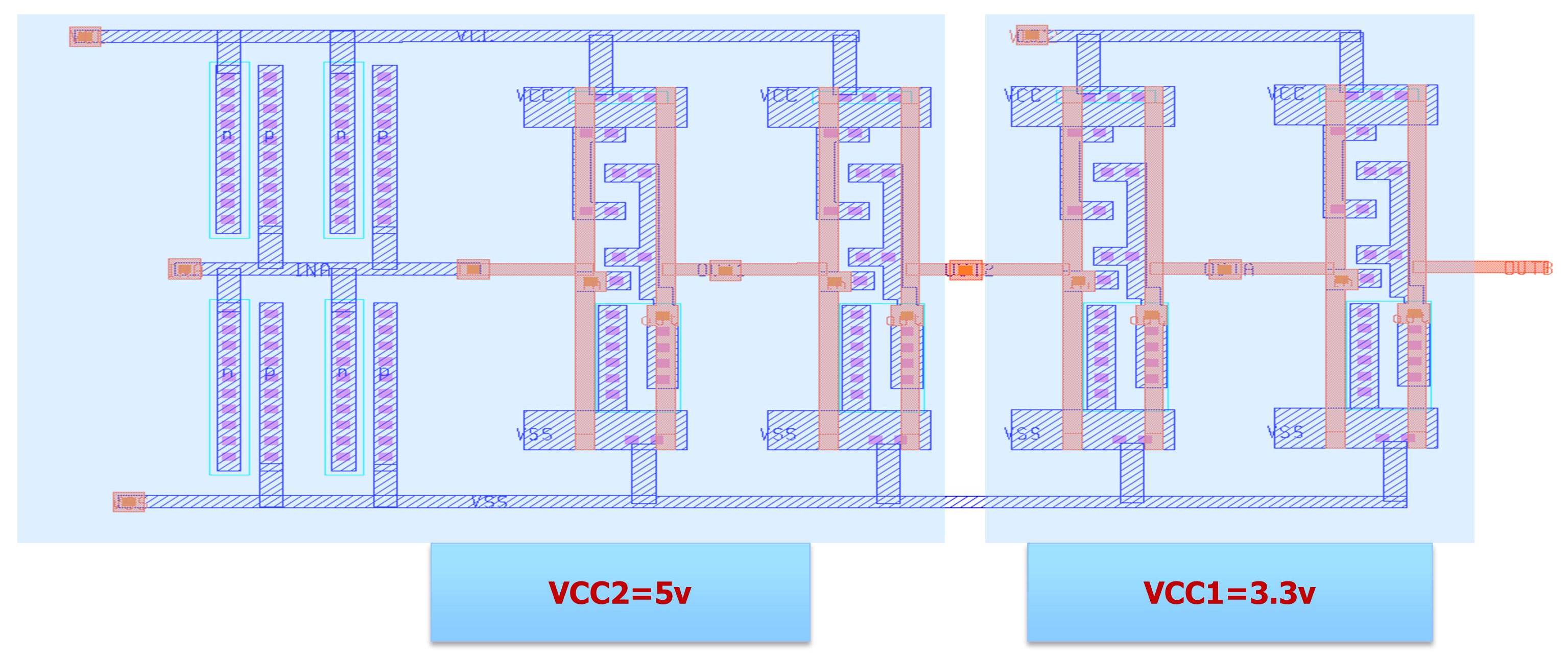
Figure 1: Using marker layers to identify regions using different voltage potentials
This approach worked very well for designs that have only a few different voltages, and the layout for the different voltage regions could be neatly contained within well-defined blocks. Also, this method depends on the designer knowing what is in each region and putting the appropriate marker layer on it…and also assumes that they have time to do so and don’t forget.
Of course, life in the IC design world isn’t quite so simple any longer. There are more voltages, and many, many more power domains. Also, to save space on your die, you may need to route high-voltage lines through areas that are predominantly low-voltage. These factors demand finer granularity and control, which calls for a polygon-level voltage-dependent DRC checking methodology. The idea is quite simple – instead of putting a marker layer over an area, simply put voltage information on the polygons so that the verification tools can calculate the most appropriate spacing rule based on the actual min/max voltage range that a pair of neighboring polygons will experience. See Figure 2 for a simple depiction.
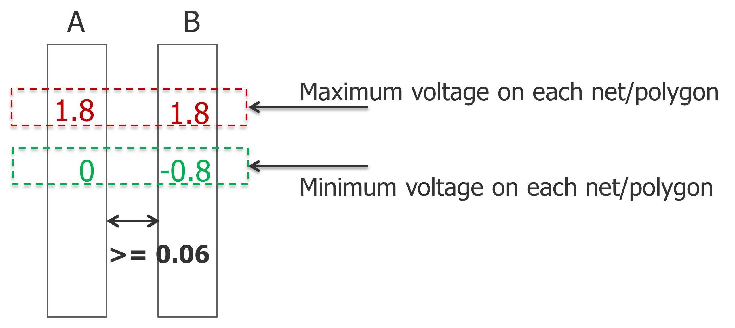
Figure 2: Polygon-level voltage information for voltage-dependent DRC
When using such a methodology, the DRC tool can use the actual min/max voltage information to decide which minimum spacing rule to apply. For instance, if the maximum possible voltage difference between two adjacent lines is 1.5V, then apply spacing X rule. If the maximum voltage difference is 2.1 volts, then apply spacing Y rule. With this type of polygon-level checking, it is possible to minimize the required area for a circuit, and ensure that the manufacturing limits are obeyed.
The obvious challenges that this methodology presents are that the max/min voltages have to somehow be derived and then annotated onto each net within the layout. You need a methodology to generate the voltages for the nets. Once the voltages have been generated, they have to get annotated onto the layout. The layout engineer certainly isn’t going to spend his life putting text on every polygon on the layout. How to do that in an automated fashion?
The methodology to generate the max/min voltages per net will depend on the design flow. For analog designs where SPICE simulations are readily available and cover the complete dynamic range for each node, it is possible to extract the max/min voltages per net from the existing simulation flow. For digital designs, it may be more challenging to excite the complete dynamic range for every net.
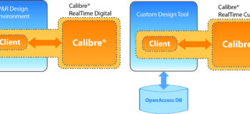
For digital designs, therefore, we recommend using an automated tool to propagate the voltages from pins to all of the internal net. It should be able to propagate voltages from each of the pins to the internal nodes, thus providing the full dynamic range for each internal net. The tool can then automatically annotate the max/min voltages for each net onto the layout and run the full sign-off DRC deck. This flow is shown in the top portion of Figure 3.
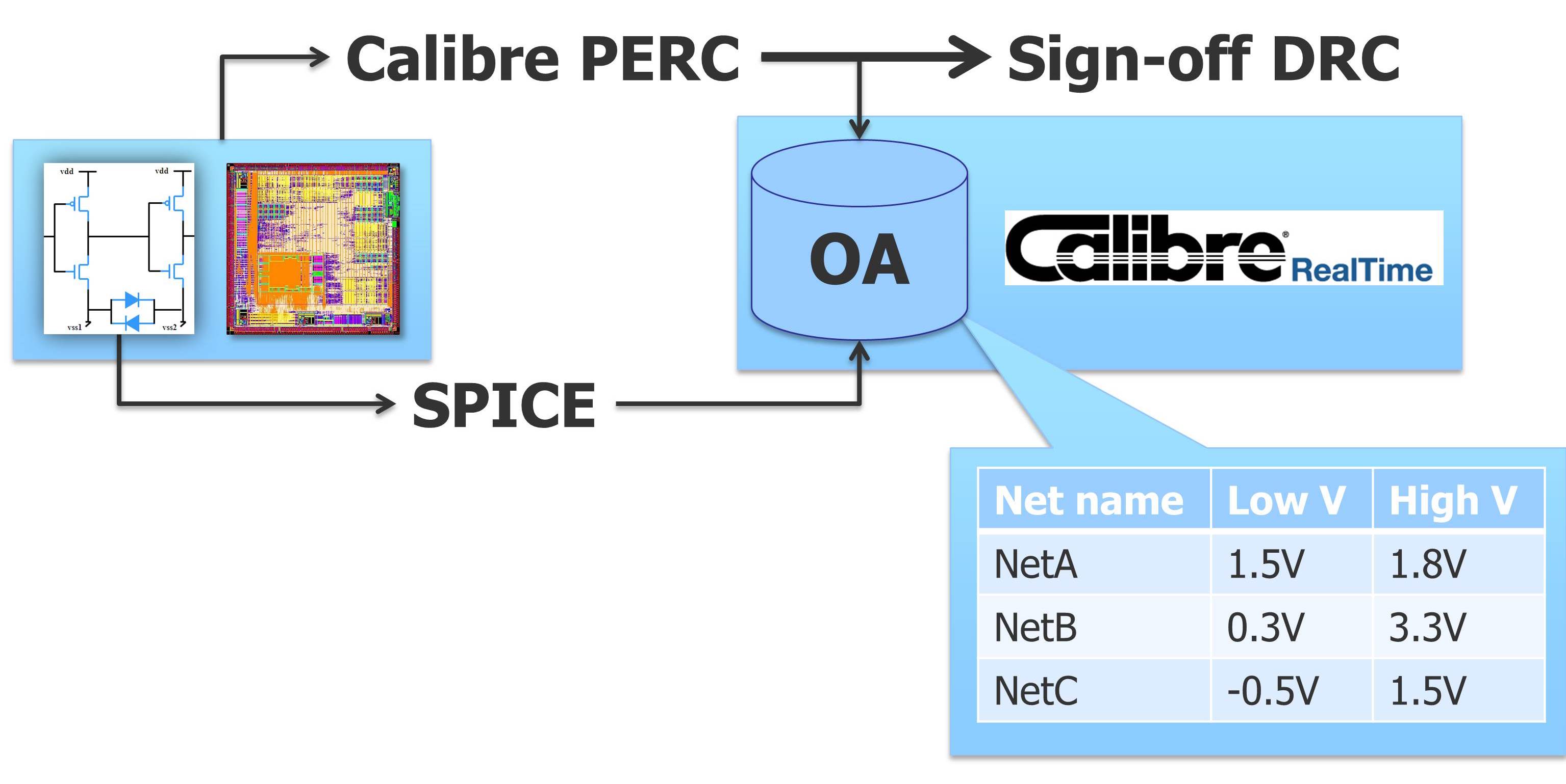
Figure 3: Voltage-Dependent DRC flow for sign-off and interactive fixing. Using the combination of Calibre PERC and Calibre nmDRC gives you a complete flow to generate the required voltage information on the implemented layout and then verify the result against the foundry’s signoff DRC deck.
Errors from this flow can then be highlighted back into the design environment, as with any other verification error. However, the result only has the information on the error itself – the voltage difference and the associated error polygon. In order to eliminate the error, the layout engineer wants to know more about the context of the error. For instance, the error touches two nets, the voltage difference is 2.2V, and the space should be X…but where does this voltage difference come from? Which polygon belongs to which net and has which voltage? This information is present in the verification flow, but not in the design environment or in the results.
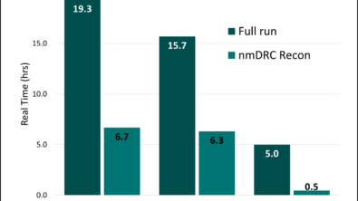
Luckily, you can export the voltage and net information in a format that can be imported into the OpenAccess database as a set of constraints. You should get a tool that can recognize this information, provide it to the user interactively, and can add this voltage information to the polygons for interactive verification. The video in Figure 4 shows how this works for one tool, Calibre RealTime. Combining the right automation tools with the custom design environment provides a complete system for implementing, optimizing, and verifying voltage-dependent layout, resulting in smaller, more efficient layout and ultimately saving both money and time for your multiple-voltage domain project.
Figure 4. Calibre RealTime voltage-dependent DRC checking.
Author
Joe Davis is Mentor’s Director of Product Marketing for Calibre interactive and integration products.

Liked this article? Then try this-
Video: How to run Voltage-Dependent DRC (VD-DRC) checks using Calibre RealTime
White Paper: Improve Reliability with Accurate Voltage-Aware DRC
This article was originally published on www.eetimes.com