UALink over UCIe 3.0: Maximizing Performance for Chiplet-based Designs

This blog is about how UALink and UCIe 3.0 come together to make chiplet‑based accelerator systems scale efficiently. It explains, in practical terms, how UALink handles accelerator‑level communication while UCIe reliably carries that traffic across die boundaries. The discussion focuses on real system challenges such as flow control, credit exhaustion, link retraining, and clean recovery without full resets. It also highlights how standardized management and capability discovery help keep large systems debuggable and predictable. Overall, the blog offers a clear architectural perspective aimed at engineers designing high‑performance AI and HPC platforms.
Introduction
With the rapid AI strides, scaling AI models is no longer limited to adding more compute capability. It is more about the performance of these models and how efficiently accelerators connect, coordinate, and operate as a system.
UALink protocol is a scale-up interconnect protocol designed to provide high‑bandwidth, low‑latency communication between accelerators and comes with well‑defined transport, flow control, and recovery behaviour.
As designs move to chiplet-based architecture, processes occurring at die boundaries, such as reliable transport, controlled backpressure, predictable bring-up, and recovery under load, dominate the system behaviour. This is where UCIe plays a crucial role. UCIe protocol provides the standardized die-to-die transport required to cross these boundaries, whereas UALink provides the accelerator-level semantics.
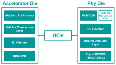
The following diagram shows the UALink-over-UCIe chiplet architecture and how the work between the two protocols is divided across the die.
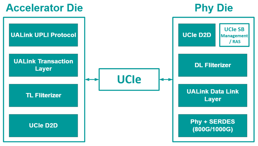
The UALink Chiplet specification defines how UALink stations are realized in a chiplet form factor and how UALink Transaction Layer and management semantics are carried over UCIe 3.0. This establishes a clear architectural behaviour to manage flits, credits, resets, and overall operations. A UALink station is a group of four UALink lanes, which enables connection between multiple accelerators through ports. This type of system facilitates efficient data transfer across several accelerators.
What does UALink over UCIe 3.0 achieve?
The UALink protocol defines a clear architectural contract for disaggregated accelerator designs.
In a typical UALink chiplet deployment, the UALink PLI layer and the Transaction Layer (TL) operate on the accelerator die, and the UALink Data Link (DL) and PHY layers are implemented on a companion chiplet. The UCIe 3.0 mainband transports the TL traffic across the chiplet boundary while the sideband supports discovery, management, and system events.
This approach separates the protocol logic from the physical implementation, without breaking the UALink’s scale-up model. Also, this approach defines how the boundary performs in situations that involve peak bandwidth utilization.
Why Credits, Retrains, and Reassembly Matter?
In large AI and HPC deployments, peak bandwidth utilization is not the major problem. The major problems show up later; some of the pertinent ones are:
- What happens when credits are exhausted, and traffic backs up?
- What happens when the die-to-die link retrains under load?
- How to replay and reassemble partially received data correctly?
- How to perform bring-up and recovery without full system resets?
UALink Chiplet over UCIe 3.0 addresses these issues by:
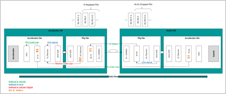
- Deterministic TL flit conversion and reassembly rules. Because the TL Flit does not align perfectly with the UCIe Flit, segmentation and reassembly are mandatory and must follow the defined packing pattern. The receiver is responsible for reconstructing TL flits and respecting per-TL ordering requirements.
- Explicit, cross‑layer credit propagation.
- During UCIe retrain, RX DL may discard incoming flits, with TX DL replay used to recover according to defined replay rules. Buffer sizing guidance and replay-time expectations define practical limits for recovery.
- Reset coordination and operational hooks for real bring‑up flows.
This elevates behaviours and processes that are often considered as implementation details into architecturally defined, interoperable behaviour. The following diagram illustrates this.
How to Deploy N UALink Stations over N/2 UCIe Link?
One of the common scaled-up deployments includes two UALink stations over a single UCIe x64 die-to-die link. This lets the system designers to:
- Scale bandwidth by replicating stations
- Optimize PHY placement and process selection
- Reduce package complexity while maintaining deterministic behaviour
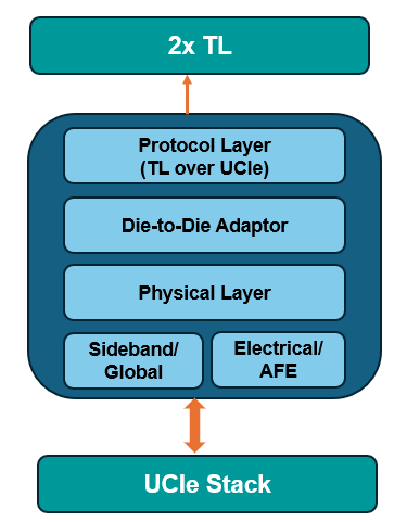
This results in deploying flexible, repeatable building blocks for a multi-accelerator system, which can be scaled without introducing uncontrolled corner cases.
How to Configure the UALink Station for Bandwidth and Efficiency?
In chiplet systems, UCIe must be sized not just for peak rate, but for predictable utilization as UALink station count scales. The two crucial factors, bandwidth and efficiency, need to be taken care of at both protocol levels.
For bandwidth, station type and count determine the aggregate TL bandwidth requirement, whereas the aggregate station bandwidth maps directly to the required UCIe D2D capacity. The UCIe sizing, which includes the width, speed, and instances, follows the UALink station configuration. The UCIe-S and UCIe-A deployments can be done where applicable. This approach enables calculable, architecture‑driven UCIe bandwidth sizing.
For Efficiency, TL flits(64B) do not align naturally with UCIe flits(256B) and are segmented and packed according to the defined TL‑to‑UCIe flit pattern. However, UCIe protocol metadata and the TL header information, such as Station ID, Port ID, credit information, and Link data, contribute to the overall transport overhead(18B), which affects the delivered throughput, while the flow-control behaviour influences effective utilization under load.
Why do Management, Capability Discovery, and RAS Matter?
In real chiplet systems, management is not just a bring‑up concern. The real challenges, some of which are given here, emerge once systems scale and operate continuously:
- When software must discover chiplet capabilities without hard‑coded assumptions?
- When buffer sizes and credit limits must be understood to avoid overload conditions?
- When errors and health events must be reported while the data path is under load?
- When should the resets and recovery be coordinated without halting the entire system?
These scenarios ultimately determine whether a system can be debugged, recovered, and operated predictably at scale.
To address this, UALink over UCIe 3.0 defines a dedicated management plane instead of relying on vendor‑specific or ad‑hoc mechanisms.
- During initialization, the software reads the standard UCIe capability registers along with the UALink‑specific capability register to discover supported features, buffer sizes, and flow‑control behavior.
- Chiplet‑specific RAS conditions are reported via registers on the accelerator die, allowing software to react to errors and status events.
- Based on these events, software can initiate targeted recovery actions—at the port, station, or full‑chiplet level—without disrupting the entire system.
Summary
UALink uses the UCIe 3.0 standard as its physical die-to-die interconnect layer, enabling chiplet-based devices to communicate efficiently. It provides a low-latency, high-bandwidth connection between GPUs and accelerators within AI pods. By standardizing interfaces, form factors, and flow control mechanisms, UALink over UCIe 3.0 improves cross-vendor interoperability and enables the development of scalable AI systems.
By: Sriram Bhaskar Mundru