The configurability dilemma creating safe ICs

A traditional automobile today consists of multiple systems controlling everything from the interior atmosphere to drive train to more advanced ADAS and AV systems. Each of these systems is specialized to perform a specific function and at the heart of these systems is often an electronic control unit (ECU) or domain controller (DCU) with complex integrated circuits. While these systems remain specialized, the silicon providers to these systems strive to provide sufficient configurability to serve multiple end applications.
Yet, each OEM and Tier 1 requirements are different. To maximize business potential, semiconductor and IP providers create Safety Element out of Context (SEooC) designs. And to capture as many customers as possible, deliver highly configurable products to support a multitude of use cases in automotive as well as use cases in other vertical markets. For example, you will find PCIe and Ethernet Switches in many markets, including automotive, where those switches can have different numbers of ports, different speeds, and different features. Silicon and IP providers need to maximize their investments by creating easy to create variants and generational updates. Variants add lifecycle complexity in other ways which we will address later on in this series.
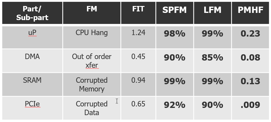
Unfortunately, configurability can add significant overhead when delivering an ISO 26262 compliant product. The primary reason is that safety analysis is an instance based analysis, meaning that safety analysis is performed on a specific configuration of the IP or IC. Said another way, safety has to be shown on each and every flavor of the design that is marketed to a customer. An ASIL-D eight port Ethernet Switch with management has to meet its safety metrics (SPFM, LFM, PMHF) while a derivative part that might be based on the same overall RTL but is unmanaged also has to be shown to meet its ASIL target. Furthermore, configurations that are under the control of the end customer also need to be analyzed. For instance, if capabilities within the design can be switched on/off from the default, the resulting configuration in the OEM’s/Tier 1’s usage has to be demonstrated to be safe.
Overview of Configurability
IP or IC configurability comes in three primary forms.
| Type | Description |
| Build-time Configurability | The ability to alter the actual hardware implementation by modifying ‘defines, design parameters, or equivalent. This could be the alteration, addition, or removal of hardware functions and/or safety features. |
| Bonding Configurability | The ability for the silicon vendor to only expose certain capabilities to the integrator. This could be based on packaging where the same die is used but only certain functions are brought to the IOs. The use of fuses during manufacturing is also a method to disable features from being seen by the end customer. |
| Run-time Configurability | The ability to turn on/off design functions and/or safety features during run-time operation via register control bit. This is visible to the end customer and controlled by firmware drivers. |
In these cases, either the silicon vendor or the integrator have to determine that the new variant or specific configuration meets their FIT (PMHF) and architectural metrics (SPFM/LFM) targets. The more variants and configurations, the larger the safety analysis work becomes.
Challenges w/ Configurability
As mentioned above, the integrators of an IP or IC must evaluate safety based on the specialization/configuration of that IP/IC. One configuration has the potential to have a completely different set of safety metrics from another configuration. Let’s run through two common examples:
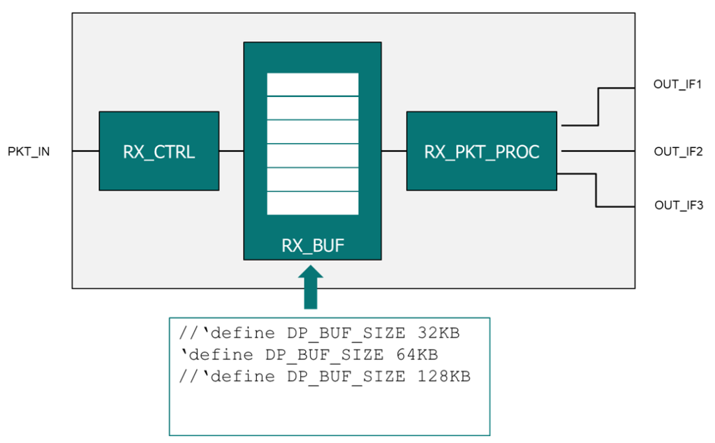
Example 1: Changing a buffer size using a define
It is common for the integrator of an IP to modify a buffer size to support the end-use application (let’s say from 32KB to 64KB). This parameter change has a direct impact on the silicon as additional memory bits are being added to the design. The addition of hardware therefore has a direct impact on the failure rate (FIT) of the design and potentially affects safety metrics such as the Single Point Fault Metric (SPFM) and Latent Fault Metric (LFM). For instance, increasing or adding to a design element that is not well protected will have a negative impact on that specific configuration’s architectural metrics.

Example 2: Turning off a safety feature of an IC
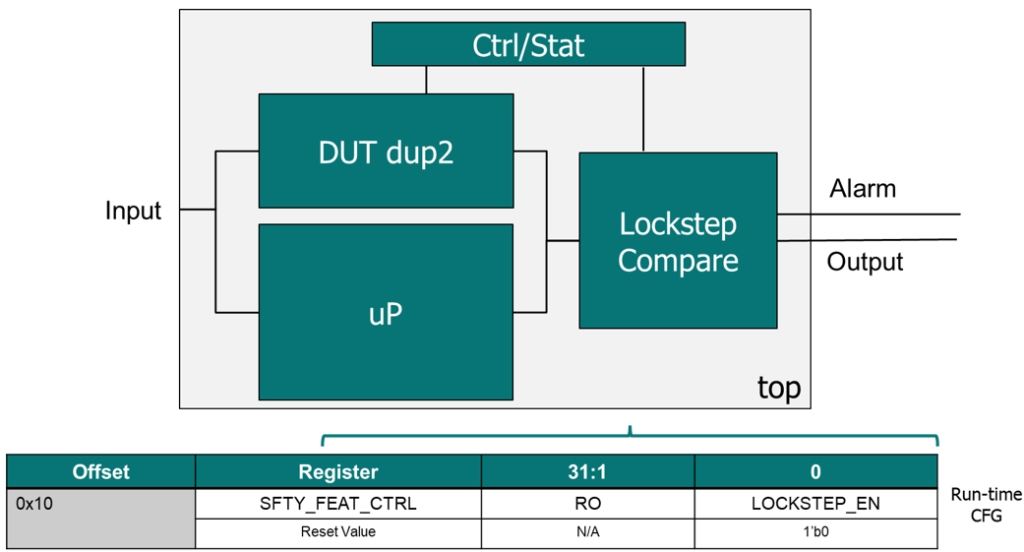
Oftentimes, an integrator will evaluate the safety features of an IC and determine that a safety feature isn’t needed due to system level protections in place or the end use case (such as checksums and CRC). This is especially true if the safety feature has a performance impact that the integrator wants to minimize. In this instance, the integrator will deactivate the safety feature via a register bit write during a start-up sequence. Similar to the previous example, the deactivation of this safety feature has a direct impact on the safety metrics of the IC.

| Best Practice: In the above example, an IC developer will likely have assumed in their Safety Analysis that the lockstep is enabled for them to claim ASIL D compliance. This goes for almost all safety mechanisms in the IC. The best practice is to enable all safety mechanisms by default. This puts the burden on the integrator to specifically disable safety mechanisms and prevents safety issues by an omission of an enabling step. |
Configurability Conflict between Supplier and Integrator
In a perfect world, IC and IP suppliers would provide a safety case (including safety metrics) for each specialization possible. The work product commonly affected by configurability is the Failure Modes and Effects Diagnostic Analysis (FMEDA). The FMEDA contains the safety metrics required by ISO 26262 to prove the design is safe from random hardware failures. The FMEDA is a part of the broader safety case and is a deliverable from supplier to integrator.

Practically, it isn’t possible to deliver a safety case and FMEDA for each specialization as there are often thousands of permutations possible. Today, suppliers often deliver a safety case for the anticipated worst case, but realistic, specialization. As an example, this configuration would have all processing cores activated, maximum buffer and data path widths, all special functions enabled (encryption, compression). Unfortunately, this puts the onus on the integrators to modify the safety case and metrics based on their unique configuration. The task of modifying the safety data based on the end use application is often challenging as it requires integrators to understand the impact of modifications on a 3rd party IP/IC. In most cases, this activity also requires suppliers to be heavily involved in assisting the integrator.
Conclusion
Whether you are a supplier or integrator, configurability has the ability to impact engineering schedule and resources. As a supplier, it is important to understand the expectations of integrators regarding the delivery of the safety case and ISO 26262 work products. Likewise, an integrator must understand if the delivered safety case will be specialized to the end-use case or if the safety case requires modification. Fortunately, automation can drastically reduce the overhead incurred with configurable IP/IC.
If you are interested in learning how Siemens software automation tools address the configurability dilemma, please reach out to your local sales team or go here.
Other Topics
This post is part of a broader safety series highlighting the challenges practitioners face during the development of safety critical ICs. To view other posts in the series, please refer to Guidelines to a successful ISO 26262 Lifecycle.


